
Finite Element Method (FEM) Explained for Mechanical Designers: Basics, Benefits and Use Cases
Ever had a design that looked flawless in CAD—only to unravel once it reached production?
For mechanical designers, few things are more frustrating than seeing a design that looked perfect on screen fail in the real world. Parts deflect more than expected, housings crack under load, assemblies drift out of tolerance, or suppliers push back on geometry that seemed reasonable in CAD. These failures rarely stem from a lack of creativity. They come from invisible assumptions about how a part will actually behave once forces, constraints, and variability are introduced.
The finite element method has become one of the most important tools designers can use to expose those assumptions early. Once considered the domain of analysts and simulation specialists, FEM is now deeply embedded in modern design workflows. For designers, FEM is no longer just about validation at the end of a project—it is about making better decisions while the design is still flexible and inexpensive to change.
This blog explains FEM from a mechanical designer’s perspective, focusing on how it supports design decision making, improves material selection in product design, helps prepare CAD for manufacturing, and reduces risk as projects move from prototype to production through stronger design for manufacturability.
What Is the Finite Element Method, Explained for Designers
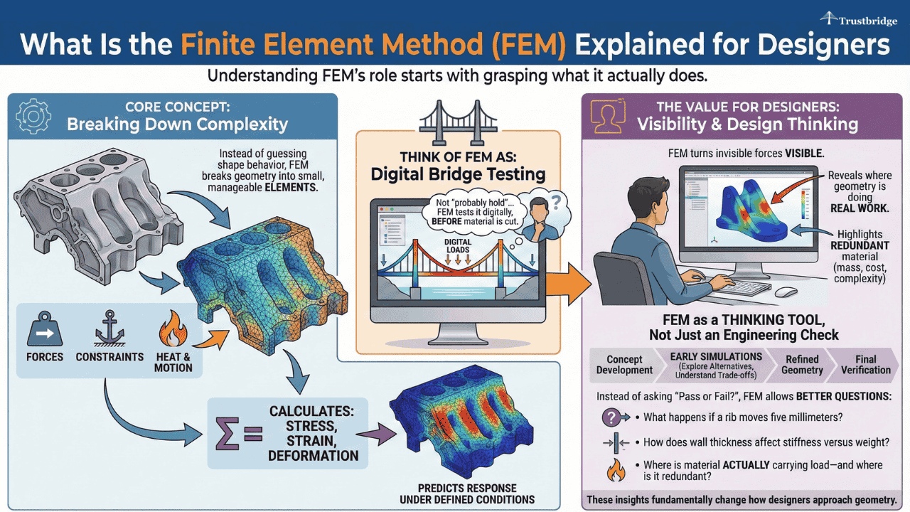
Understanding FEM’s role starts with grasping what it actually does.
At its core, the finite element method is a way to predict how a part will respond to forces, constraints, heat, and motion by breaking complex geometry into small, manageable elements. Instead of guessing how a shape behaves, FEM calculates how stress, strain, and deformation distribute across the part under defined conditions.
A useful way to think about FEM is like testing a bridge by modeling how every beam and joint carries load, rather than assuming the structure will “probably hold.” FEM does this digitally, long before material is cut.
For designers, the value of FEM is not the mathematics behind it. The value lies in visibility. FEM turns invisible forces into something designers can see and reason about. It reveals where geometry is doing real work—and where it is simply adding mass, cost, or manufacturing complexity.
FEM as a Design Thinking Tool, Not Just an Engineering Check
When FEM is treated only as a final verification step, its value is limited. When designers use FEM during concept development, it becomes a thinking tool. Early simulations help designers explore alternatives quickly, understand trade-offs, and refine geometry before the cost of change rises.
Instead of asking whether a design passes or fails, FEM allows designers to ask better questions:
• What happens if a rib moves five millimeters?
• How does wall thickness affect stiffness versus weight?
• Where is material actually carrying load—and where is it redundant?
These insights fundamentally change how designers approach geometry.
What Mechanical Designers Actually Use FEM in the Design Process
This shift in mindset is what makes FEM a design tool rather than just a validation tool.
In practice, designers use FEM to guide decisions long before drawings are released. It supports intuition with evidence and replaces guesswork with informed judgment.
FEM and Early Design Decision Making
Every project is full of decisions that feel small but have lasting consequences. Choosing between two geometries, adjusting fillet radii, or deciding whether a part can be thinner all affect performance and manufacturability. FEM allows designers to test these decisions digitally before committing to tooling or prototypes.
For example, a housing wall that looks sufficiently thick in CAD may show excessive deflection under assembly loads when simulated, prompting an early geometry change instead of a late redesign.
This shifts design decision making from reactive to proactive. Instead of discovering weak points during testing or production, designers can anticipate them while changes are still inexpensive—saving time, cost, and rework downstream.
FEM in Material Selection in Product Design
Material selection is where FEM quickly proves its value to designers.
Material selection in product design often starts with requirements like strength, weight, and cost. FEM allows designers to go deeper by comparing how different materials behave in the same geometry.
For instance, a bracket that performs well in aluminum may fail stiffness requirements in a glass-filled polymer, even if strength appears adequate on paper. FEM reveals these differences early.
By simulating materials early, designers can align performance expectations with real behavior. This reduces the risk of late material changes that ripple through tooling, suppliers, and schedules—ensuring designs meet performance goals without costly redesigns.
Using FEM to Prepare CAD for Manufacturing
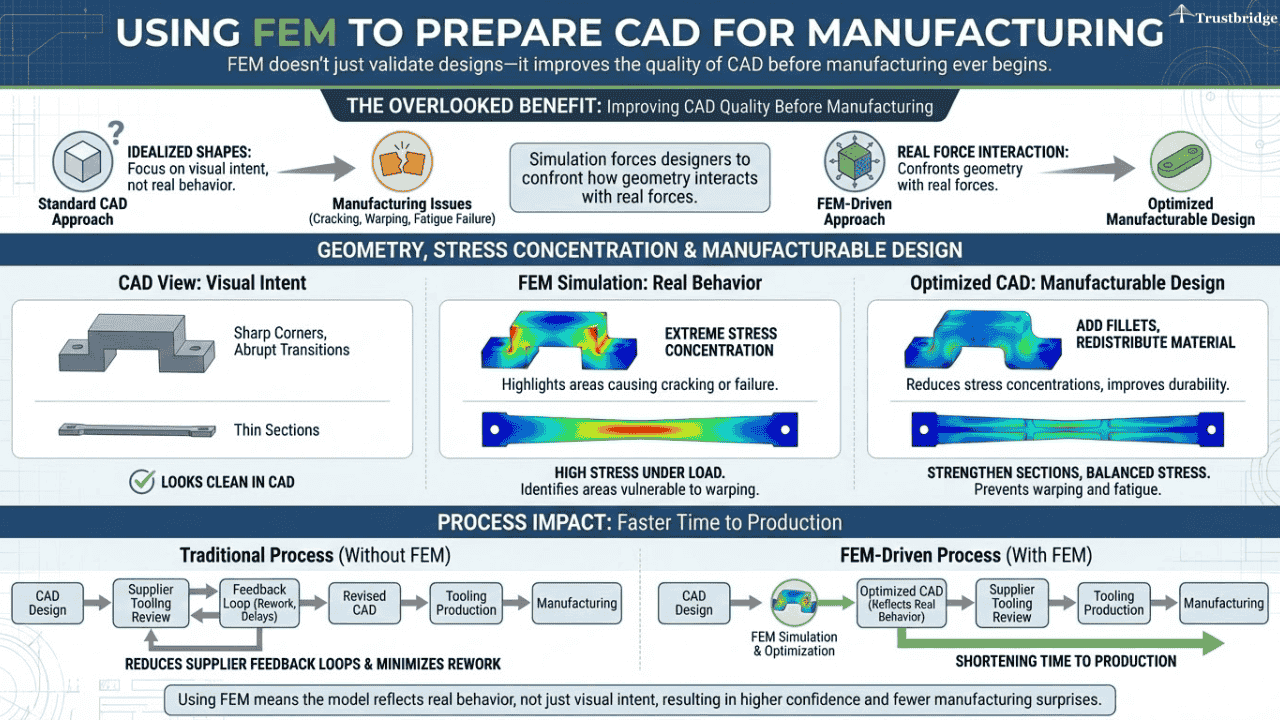
FEM doesn’t just validate designs—it improves the quality of CAD before manufacturing ever begins.
One of FEM’s most overlooked benefits is how it improves CAD quality before manufacturing. Simulation forces designers to confront how geometry interacts with real forces rather than idealized shapes.
Geometry, Stress Concentration, and Manufacturable Design
Sharp corners, thin sections, and abrupt transitions often look clean in CAD but concentrate stress in ways that cause cracking, warping, or fatigue failure. FEM highlights these areas immediately.
For example, a sharp internal corner that looks acceptable in CAD may show extreme stress concentration under load, guiding the designer to add fillets or redistribute material.
Using FEM to prepare CAD for manufacturing means the model reflects real behavior, not just visual intent. This alignment reduces supplier feedback loops and minimizes rework during tooling review—shortening time to production.
FEM Across the Prototype to Production Transition
The transition from prototype to production is where many designs quietly fail.
Many designs perform well in prototypes and fail in production. This gap is not accidental. It is structural.
Why Prototypes Lie and Production Doesn’t
Prototypes are forgiving. They are built slowly, handled carefully, and tested under controlled conditions. Production introduces cycle time pressure, thermal variation, assembly forces, and repeated use.
For example, a prototype enclosure may survive low-cycle testing but crack in production when exposed to repeated assembly stress and temperature variation.
FEM helps designers anticipate these realities before they appear on the shop floor. By evaluating worst-case scenarios rather than ideal conditions, designers can ensure parts survive the transition from prototype to production—reducing late-stage failures and emergency redesigns.
Trustbridge Tip: FEM helps designers validate stress, deflection, and material behavior—but releasing a part for CNC machining, especially in aerospace, requires more than simulation confidence. Tolerances, datum structure, machining strategy, and how loads are introduced during fixturing and assembly all affect whether a “passing” design actually survives production. Using FEM early ensures your design is physically sound; aligning it with CNC-ready release practices ensures it is manufacturable at scale. To understand what designers must evaluate before sending aerospace parts to the shop floor, read our related guide: What Must Designers Consider Before Releasing Aerospace Parts for CNC Machining?
FEM as a Core Part of Design for Manufacturability
Design for manufacturability starts with physics, not checklists.
Design for manufacturability is often framed as a manufacturing concern. In reality, it begins with design decisions. FEM strengthens DFM by grounding it in physics rather than rules of thumb.
Designing for Real Loads, Not Idealized Assumptions
Designers frequently underestimate real-world loads introduced during assembly, shipping, or use. FEM exposes these forces early. It shows how parts flex during installation, how fasteners introduce stress, and how repeated loading leads to fatigue.
When FEM informs design for manufacturability, designers create parts that are easier to produce, assemble, and scale. Manufacturing stops being a constraint and becomes a predictable extension of design intent—leading to smoother production ramps and fewer surprises.
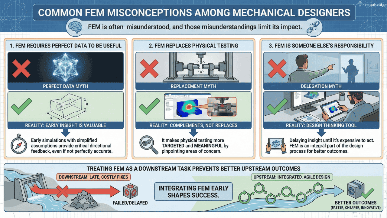
Common FEM Misconceptions Among Mechanical Designers
FEM is often misunderstood, and those misunderstandings limit its impact.
Common misconceptions include:
• FEM requires perfect data to be useful — early simulations are valuable even with simplified assumptions
• FEM replaces physical testing — it doesn’t; it makes testing more targeted and meaningful
• FEM is someone else’s responsibility — delaying insight until it’s expensive to act
Treating FEM as a downstream task prevents designers from shaping better outcomes upstream.
Conclusion:
The finite element method is no longer optional for mechanical designers working on real-world products. It is a core design capability.
Designers who use FEM early make better decisions, choose materials more confidently, prepare CAD for manufacturing more effectively, and reduce risk as projects move from prototype to production.
FEM does not replace creativity. It protects it. It ensures that what designers imagine can survive contact with physics, manufacturing, and scale—without costly surprises.
If your designs are strong in concept but struggle in production, the issue is rarely creativity. It is visibility.
Use FEM earlier. Let it guide design decision making, support material selection in product design, and shape geometry before manufacturing locks it in. Treat simulation as a design tool not a last-minute safety net.
Frequently Asked Questions (FAQs)
1. What is the finite element method, in simple terms for mechanical designers?
The finite element method is a simulation approach that shows how a design will behave under real forces, constraints, and loads. It breaks complex geometry into small elements, so designers can see stress, deformation, and weak points early before prototypes or tooling are created.
2. When should mechanical designers use FEM in the design process?
FEM delivers the most value when used early, during concept development and geometry refinement. Running simulations before designs are finalized helps designers make better decisions while changes are still inexpensive, reducing late-stage redesigns during prototyping and production.
3. How does FEM improve material selection in product design?
FEM allows designers to compare how different materials behave in the same geometry. A material that looks acceptable on a datasheet may fail stiffness or deflection requirements in practice. FEM exposes these differences early, preventing late material changes that disrupt tooling and schedules.
4. How does FEM support design for manufacturability and production scale?
FEM reveals how parts respond to real assembly forces, repeated loading, and manufacturing variability. By designing for real loads rather than ideal assumptions, designers create geometry that is easier to manufacture, assemble, and scale consistently from prototype to production.