
Aerospace CNC Machining: Design Requirements, Tolerances, and Precision Manufacturing Standards Designers Must Consider
In aerospace product development, design decisions must withstand extreme scrutiny. Components are expected to perform reliably under vibration, thermal cycling, pressure variation, and strict regulatory oversight. For designers, aerospace CNC machining is not a downstream manufacturing activity—it is a fundamental design constraint that influences geometry, material choice, tolerance strategy, and documentation from the earliest stages.
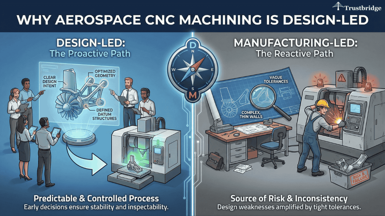
Why Aerospace CNC Machining Is Design-Led Rather Than Manufacturing-Led
Aerospace CNC machining reveals design weaknesses more aggressively than most manufacturing processes. Tight tolerances, thin walls, and complex geometries amplify even small design inconsistencies, making early design decisions critical to production success.
Designers determine whether machining will be stable, repeatable, and inspectable by defining geometry, datum structures, and tolerances. When design intent is clear and manufacturable, aerospace CNC machining becomes a predictable and controlled process rather than a source of risk.
Example
Design for Manufacturability in Aerospace CNC Machining
In aerospace programs, manufacturability directly impacts cost, quality, and schedule. Design for manufacturability ensures that parts can be machined accurately, fixtured securely, and inspected consistently across multiple production runs. For designers, manufacturability is not a compromise—it is a requirement for precision and reliability.
Integrating Design for Manufacturability at the Concept Stage
Applying design for manufacturability early prevents performance-driven designs from becoming production bottlenecks. Aerospace components are often machined from expensive materials, making rework and scrap especially costly.
Designers must consider tool access, cutting forces, and part rigidity during machining. Features such as deep cavities, unsupported walls, and aggressive weight reduction can introduce vibration or distortion if not carefully balanced with machining realities.
Geometry Decisions That Enable Precision Machining
Stable aerospace CNC machining depends on geometry that supports consistent fixturing and datum alignment. Designers who provide clear reference surfaces reduce tolerance stack-up and improve repeatability.
Example
CNC Machining Used to Produce Satellite and Landing Gear Parts
A case study describing how advanced 3-axis and 5-axis machines help aerospace manufacturers produce satellite brackets, landing gear components, and complex structural parts under tight tolerances.
Tolerance Strategy and ISO 2768 in Aerospace Design
Tolerances define how aerospace components function, assemble, and are validated. A clear tolerance strategy communicates design intent while balancing functional requirements with realistic machining capability. Poor tolerance decisions often lead to unnecessary cost or quality disputes.
Understanding ISO 2768 in Aerospace CNC Machining
ISO 2768 specifies general tolerances for dimensions that are not explicitly defined. In aerospace CNC machining, designers must apply ISO 2768 carefully to avoid unintended variation in critical features.
Functional interfaces, load-bearing elements, and mating surfaces should always have explicit tolerances rather than relying on default standards.
Avoiding Over-Tolerancing While Preserving Performance
Over-tolerancing increases machining time, inspection effort, and rejection rates without always improving part function. Designers should apply tight tolerances only where safety, fit, or performance truly depend on them.
A disciplined tolerance strategy improves both manufacturability and production efficiency.
Material Selection in Product Design for Aerospace CNC Machining
Materials define not only performance characteristics but also machining behavior. Material selection in product design directly influences cutting stability, thermal distortion, and final dimensional accuracy in aerospace CNC machining.
Designers must evaluate materials based on machinability alongside strength, weight, and environmental resistance.
Designing With Machinability in Mind
Aerospace materials such as aluminum alloys, titanium, and engineered polymers respond differently to heat and cutting forces. Materials with poor thermal conductivity or high work-hardening tendencies can distort during machining.
Effective material selection in product design balances mechanical requirements with predictable machining behavior to ensure dimensional stability.
Accounting for Surface Treatments and Finishing
Processes such as anodizing introduce dimensional changes that must be accounted for during design. Designers should specify dimensions based on post-treatment conditions rather than raw machined states.
Failure to account for finishing often results in aerospace parts that pass machining but fail final inspection.
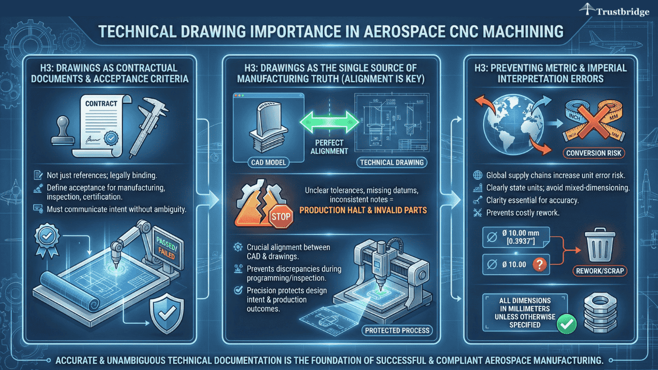
Technical Drawing Importance in Aerospace CNC Machining
In aerospace programs, drawings are not just references—they are contractual documents. Technical drawing importance is amplified because drawings define acceptance criteria for manufacturing, inspection, and certification.
Designers must ensure drawings clearly communicate intent without ambiguity or reliance on interpretation.
Drawings as the Single Source of Manufacturing Truth
Unclear tolerances, missing datum definitions, or inconsistent notes can halt aerospace CNC machining or invalidate finished parts. Designers should ensure alignment between CAD models and drawings to prevent discrepancies during programming and inspection.
Precision in documentation protects both design intent and production outcomes.
Preventing Metric and Imperial Interpretation Errors
Global aerospace supply chains increase the risk of unit conversion errors. Designers must clearly state units and avoid mixed-dimensioning unless explicitly required.
Clarity in units is essential to maintaining accuracy and preventing costly rework.
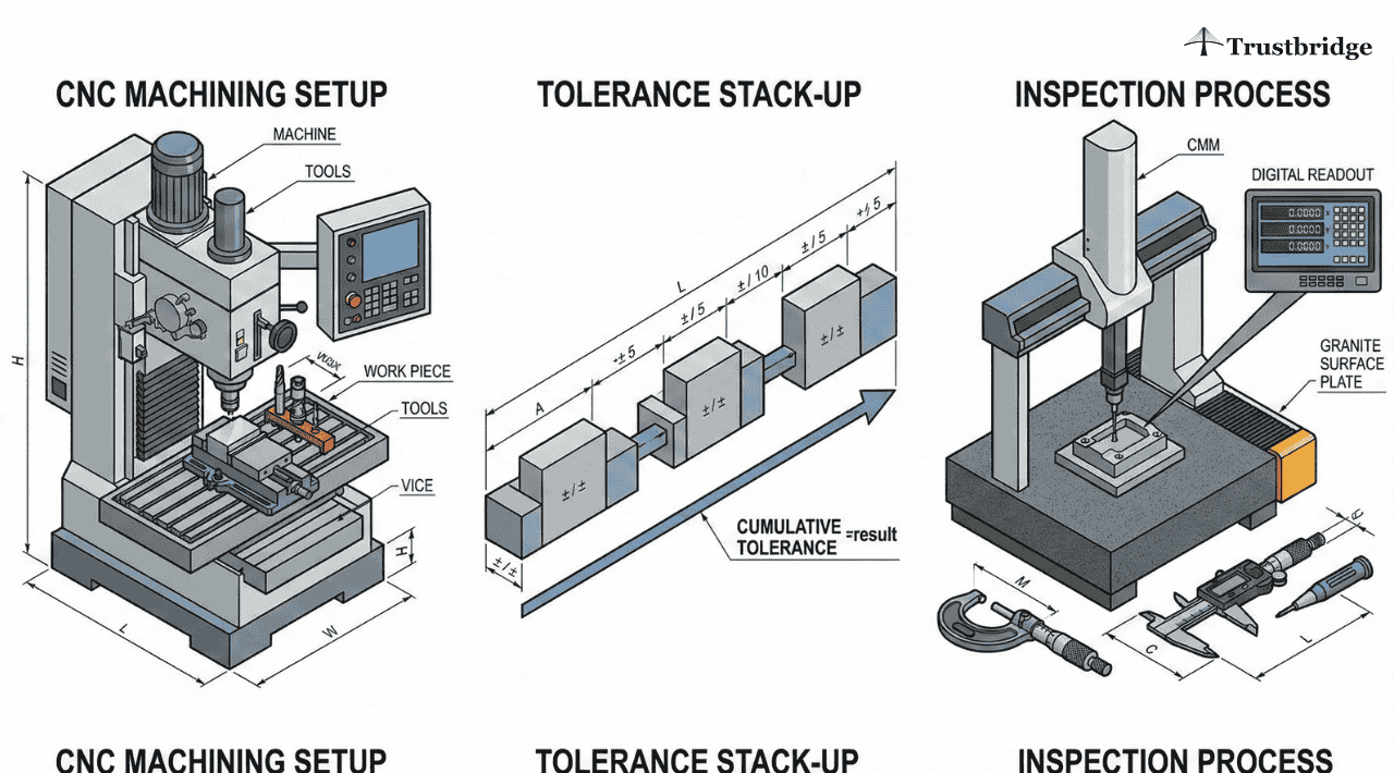
Measurement and Validation Using Coordinate Measuring Machines
Inspection is a critical step in aerospace CNC machining, and measurement capability must be considered during design. A coordinate measuring machine is the primary tool used to validate dimensional accuracy and geometric integrity.
Designers who understand inspection constraints can create parts that are easier to verify and certify.
Designing Features That Can Be Measured Reliably
A coordinate measuring machine requires accessible and stable features for accurate probing. Designs that limit probe access increase inspection time and measurement uncertainty.
Designers should ensure that critical features can be referenced and measured consistently.
Aligning Tolerances With Inspection Capability
Tolerances should reflect not only functional requirements but also measurement feasibility. Excessively tight tolerances may exceed practical inspection limits, even when machining is accurate.
Alignment between design intent and inspection capability reduces quality disputes and production delays.
CAD Quality and Its Impact on Aerospace CNC Machining
The quality of CAD data directly affects machining accuracy and programming efficiency. Designers influence CNC outcomes by creating clean, well-constrained models that translate reliably into toolpaths.
Poor geometry definition increases programming complexity and the likelihood of machining errors.
Trustbridge Tip: In aerospace CNC machining, production release issues often trace back to design gaps rather than machining capability. OEM buyers evaluate more than dimensions—they assess design for manufacturability, tolerance clarity under ISO 2768, material choices, inspection readiness using a coordinate measuring machine, and the precision of technical documentation. Designs that clearly communicate intent through accurate drawings and thoughtful material selection in product design move through buyer approval faster and with fewer revisions.
To see what OEM buyers verify before approving parts for production, read: What Should OEM Buyers Verify Before Approving a Part for Production Release?
Aerospace CNC Machining as a Collaborative Design Discipline
Aerospace CNC machining succeeds when design, manufacturing, and quality teams operate with shared understanding. Designers who account for machining and inspection realities can anticipate challenges and make informed trade-offs early. This collaboration reduces late-stage design changes and improves production predictability.
Designing Aerospace Components That Perform and Scale Successfully
Successful aerospace CNC machining begins with informed design decisions. By prioritizing design for manufacturability, applying ISO 2768 correctly, making thoughtful material selection in product design, emphasizing technical drawing importance, and accounting for coordinate measuring machine inspection, designers can create aerospace components that perform reliably and scale efficiently.
If you are designing aerospace components and want confidence that your designs will machine accurately, inspect reliably, and transition smoothly from prototype to production, manufacturing alignment must start at the design stage.
Trustbridge works closely with designers and engineering teams to bridge the gap between design intent and aerospace CNC machining reality. Connect with our experts to ensure your designs meet precision standards without unnecessary cost, risk, or delay.
Frequently Asked Questions (FAQs)
1. Why do aerospace CNC machining issues often originate at the design stage?
In aerospace CNC machining, many production failures trace back to design decisions rather than machining capability. Unclear tolerances, unstable geometries, poor datum selection, or unrealistic wall thicknesses can lead to distortion, inspection failures, and repeated rework. Designers who account for machining and inspection constraints early reduce downstream risk and accelerate production readiness.
2. How does design for manufacturability affect aerospace CNC machining success?
Design for manufacturability ensures aerospace parts can be machined, fixtured, and inspected consistently. Designs that overlook tool access, cutting forces, or part rigidity often experience chatter, dimensional instability, or excessive cycle times. Applying manufacturability principles early improves machining repeatability and shortens production approval cycles.
3. When should ISO 2768 be used in aerospace CNC machining drawings?
ISO 2768 should be limited to non-critical features where general tolerances are acceptable. Functional interfaces, safety-critical surfaces, and mating features require explicitly defined tolerances. Over-reliance on ISO 2768 can create ambiguity, resulting in parts that meet drawings but fail functional or inspection requirements.