
Injection Molding Design Guidelines Every Designer Needs to Know
When you design plastic components, your primary goal is to translate a beautiful 3D model into a reliable, cost-effective physical part. The secret weapon for making this happen is mastering Injection Molding Design Guidelines (IMDG). These aren't just arbitrary rules; they are the foundational language you use to communicate with the material, the mold, and the machine. As a designer, your job isn't done until the part can be manufactured efficiently. Ignoring these principles leads to immediate and costly defects: warping, sink marks, tooling delays, and expensive mold revisions. Following IMDG means you design with confidence, using the constraints of the process to your advantage and unlocking creative possibilities rather than being limited by them. This guide walks you through the core guidelines you should follow from a practical, designer-focused perspective.
What Are Injection Molding Design Guidelines?
Injection Molding Design Guidelines are the best practice rules for designing parts that will be manufactured via injection molding. In other words: if you design a plastic part and someone is going to mold it, then following these guidelines helps make the process smoother, cheaper and higher quality. According to experts, design for injection moldings means planning from the start how the molten plastic will flow, cool and eject from the mold.
As a designer, your goal is to make things that look good, function well, and manufacture well. The right Injection Molding Design Guidelines bridge the gap between what you dream up and what the factory can easily and reliably produce.
Why Designers Should Care About Injection Molding Design Guidelines?
When you ignore these Injection Molding Design Guidelines, you risk parts with warping, sink marks, expensive tooling changes, and long delays. For example: one guide points out that the walls of a part should be consistently thick, because inconsistent walls lead to defects.
From a designer’s perspective:
- You don’t want your beautiful concept ruined by manufacturing issues.
- You don’t want the budget to blow down because the mold has to be redesigned.
- You want your part to hit the timeline, look great, and perform well.
So, the next sections dig into key guidelines you should ALWAYS think about when designing. These are practical and friendly for a designer, not heavy engineer-only.
Guideline 1: Uniform Wall Thickness
One of the most essential Injection Molding Design Guidelines is maintaining uniform wall thickness throughout the part. Inconsistent wall thickness is one of the most common causes of defects like warping, sink marks, voids, and residual stress. When molten plastic flows into the mold, it cools and solidifies at different rates depending on the section thickness. Thick areas retain heat longer and shrink more as they cool, while thin areas solidify sooner. This uneven cooling leads to distortions and cosmetic flaws that ruin the final product’s appearance and dimensional accuracy.
To implement this guideline correctly, start by determining a target wall thickness suitable for your chosen material. For most thermoplastics, this usually falls between 1.5 mm to 4 mm, though it varies by resin. Once you’ve selected your base thickness, design all connecting features to stay as consistent as possible. If your part requires structural reinforcements or thicker sections for functionality, use gradual transitions rather than sudden changes. Taper or fillet transitions smoothly so that the material flow remains balanced during molding. Consistency in wall design not only improves mechanical performance but also helps the mold fill more predictably, ensuring a high-quality finish and faster cycle time.
Guideline 2: Draft Angles for Easy Ejection
Adding draft angles is another vital Injection Molding Design Guideline that ensures the molded part can be released easily from the mold cavity. During the molding process, plastic cools and slightly contracts, which can cause the part to grip tightly to the mold’s core surfaces. Without draft angles, the part can stick or deform during ejection, potentially damaging both the mold and the component. A well-considered draft angle allows the part to slide out effortlessly while maintaining its surface integrity.
To apply this correctly, introduce a small taper, typically between 1° and 3°, on any vertical or molded wall that aligns with the direction of ejection. The deeper the feature or the more textured the surface, the larger the draft angle required. For example, parts with deep cavities or matte finishes may require up to 5° of draft. Plan for these angles early in your CAD design rather than forcing them later, since modifying draft late in development can distort part geometry. Properly applied draft angles not only protect the mold but also reduce friction and stress on the part, ensuring consistent quality and longevity of the tooling.
Guideline 3: Ribs, Bosses and Supporting Features
Structural reinforcements like ribs and bosses play a crucial role in the performance of molded plastic parts. These features add rigidity and provide mounting or fastening points without increasing overall wall thickness. However, when designed improperly, they can lead to visible surface defects, sink marks, or incomplete fills. The Injection Molding Design Guidelines emphasize that ribs should generally be thinner than the main wall and well-integrated into the overall geometry to avoid material buildup. For example: a rib thickness should often be no more than 50-70% of the nominal wall thickness.
When implementing this correctly, aim for rib thicknesses that are about half to two-thirds of the nominal wall thickness. This proportion ensures that the ribs strengthen the part without creating excessive cooling time or shrinkage issues. Maintain smooth transitions at the rib base with generous radii to improve material flow and reduce stress concentration. For bosses used in screw joints or assembly points, avoid making them overly thick; instead, use gussets or supporting ribs around the boss to provide strength while keeping wall thickness under control. Always visualize how molten plastic will fill these features smooth; gradual shapes are more mold-friendly than abrupt changes. By following this approach, you achieve lightweight yet strong components with clean surfaces and minimal defects.
Trustbridge Tip: Struggling with costly design flaws or slow prototype turnarounds? Get expert-led Plastic Injection Molding Services that turn your CAD into production-ready parts—fast and precisely. Explore Our Injection Molding Services
Guideline 4: Fillets, Radii and Avoiding Sharp Corners
Sharp internal corners are stress magnets in injection-molded parts. They interrupt the smooth flow of molten plastic, create turbulence, and concentrate on mechanical stress, often resulting in cracks, weak points, or even mold damage. That’s why the InjectionMolding Design Guidelines strongly recommend the use of fillets and radii to smooth out all transitions between walls and features. A well-rounded corner not only makes your part stronger but also improves how plastic fills the mold, leading to a smoother, more aesthetic finish.
To apply this guideline effectively, replace sharp 90° corners with rounded edges having a radius roughly equal to at least half the wall thickness. For example, if your part wall is 2 mm thick, an internal fillet radius of around 1 mm is a good starting point. Larger radii can further enhance durability and appearance. Use consistent radii across the design to maintain visual harmony and predictable mold flow. Smooth external corners also reduce wear on the mold tooling and improve paint adhesion or surface finishing later. Incorporating fillets early in the design phase ensures your part flows better, looks refined, and performs reliably without additional cost or rework.
Guideline 5: Parting Lines, Gates and Ejector Pins
Every injection-molded part has unavoidable technical features like parting lines, gates, and ejector pins—elements dictated by how the mold opens, fills, and releases the part. The Injection Molding Design Guidelines encourage designers to embrace these realities rather than ignore them. A thoughtfully planned parting line or gate location can make the difference between a seamless-looking product and one that shows visible imperfections.
To implement this properly, collaborate early with mold engineers to determine where the mold halves will separate—the parting line. Place this line in less visible areas or along existing edges where it will be hidden in assembly or texture. Likewise, consider the placement of gates, which are the entry points for molten plastic. Their positioning affects both aesthetics and performance; a poorly located gate can cause flow marks, weld lines, or uneven filling. When it comes to ejector pins, anticipate their presence in the design by providing flat, non-cosmetic areas where pin marks won’t matter. By designing with these manufacturing realities in mind, you’ll produce parts that not only function perfectly but also retain their visual appeal straight out of the mold.
Guideline 6: Tolerances and Moldability
Understanding and applying realistic tolerances is fundamental to high-quality injection molding. Designers often fall into the trap of specifying unnecessarily tight tolerances, which may be feasible in machining but not always achievable in plastic molding. The Injection Molding Design Guidelines remind designers that every material behaves differently as it cools and shrinks, and those variations must be accounted for during design. Ignoring these material realities leads to expensive tooling changes, rejected parts, or assembly misfits.
To get this right, begin by identifying which dimensions in your part are critical to function and which allow flexibility. Consult with your mold manufacturer or reference standard tolerance tables for the specific resin being used. Many plastics have a typical shrinkage rate ranging from 0.5% to 1.5%, depending on material type and geometry. Account for these variances during modeling and avoid over-constraining features that don’t need precision. When ultra-tight tolerances are necessary, consider secondary machining or post-processing instead of pushing the mold beyond its limits. Designing with realistic, achievable tolerances keeps production efficient and costs predictable while still delivering the precision your product needs.
Guideline 7: Avoid Undercuts When Possible
Undercuts—features that prevent a molded part from being ejected directly from the mold—are notorious for complicating the tooling process. They require special mechanisms such as sliders, lifters, or collapsible cores, all of which add cost, extend lead time, and increase the risk of defects. The Injection Molding Design Guidelines recommend eliminating undercuts wherever possible or designing them intelligently, so they don’t obstruct ejection.
To implement this effectively, review your part of geometry and identify any areas that might trap the mold during ejection—such as hooks, recesses, or inward-facing lips. Where possible, redesign these shapes to allow straight pull ejection. For example, replace a hooked detail with a snap-fit that opens along the mold’s direction, or split the part into two components that assemble later. If the undercut is functionally necessary, involve tooling engineers early to explore solutions like side-actions or flexible core designs. Every adjustment that simplifies mold release pays off in shorter cycle times, lower costs, and longer mold life. By being proactive in addressing undercuts, you ensure your design remains elegant, efficient, and production ready.
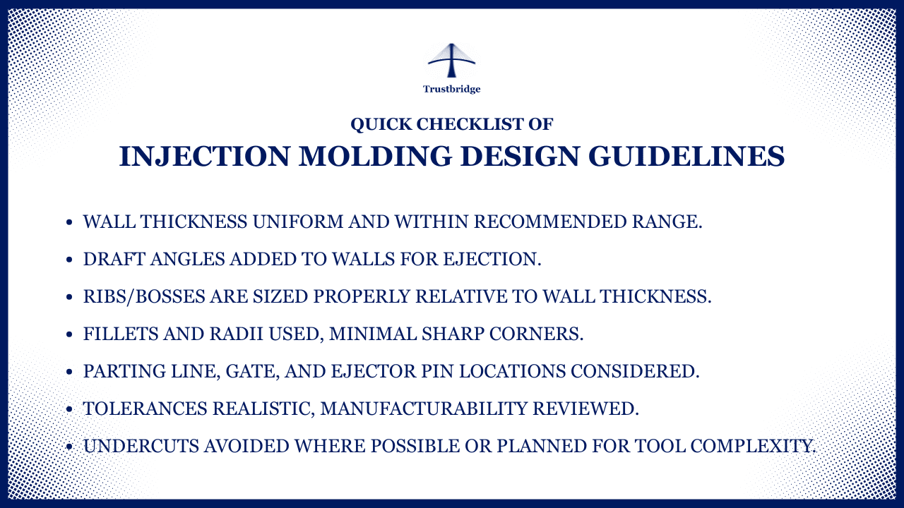
Putting It All Together: Your Designer Checklist
Before you hand off your design, run through this quick checklist of Injection Molding Design Guidelines:
- Wall thickness uniform and within recommended range.
- Draft angles added to walls for ejection.
- Ribs/bosses are sized properly relative to wall thickness.
- Fillets and radii used, minimal sharp corners.
- Parting line, gate, and ejector pin locations considered.
- Tolerances realistic, manufacturability reviewed.
- Undercuts avoided where possible or planned for tool complexity.
These cover many of the major guidelines you’ll want to apply. Each one helps you design not only for function and form, but also for manufacturability and cost.
Why These Injection Molding Design Guidelines Benefit You:
Following these Injection Molding Design Guidelines turns your designs from creative concepts into production-ready realities. When you apply these principles early, your parts are more likely to mold correctly the first time—saving both time and money. Instead of facing delays or expensive tooling fixes, your design flows smoothly through the manufacturing process. Every choice, from wall thickness to draft angle, directly impacts how easily and accurately your design becomes a finished product. That foresight means fewer surprises during production and faster turnaround from concept to market.
Beyond the technical benefits, designing these guidelines strengthens your professional credibility. Manufacturers immediately notice when a design is “tooling-aware,” which makes collaboration smoother and communication clearer. Your parts not only look refined but also perform better because the process supports your design intent rather than working against it. Ultimately, these guidelines help you achieve designs that are practical, cost-effective, and visually strong, giving you an edge as a designer who understands both aesthetics and manufacturability.
Trustbridge Tip: Before you finish your CAD model, ask yourself: Can this part be manufactured efficiently and reliably? Applying Design for Manufacturability (DFM) means thinking about tooling, processes, and material choice from the start—so you avoid cost overruns, reduce iterations, and get parts that go straight into production. Dive into the full article for the complete breakdown: “From CAD to Production: How Design for Manufacturability Defines Success.”
Conclusion
Designing injection molding is more than just making something that looks good; it’s about creating parts that can be produced efficiently, consistently, and without compromising quality. The Injection Molding Design Guidelines we explore are not just technical rules; they’re a framework for smarter, more reliable design thinking. When you understand how material flows, cools, and releases from a mold, you design with confidence and precision.
For designers, this awareness bridges creativity and manufacturability. It means fewer production issues, stronger relationships with engineers and vendors, and final products that truly reflect your intent. Keep these principles at the heart of your workflow, revisit them often, and you’ll find that great design doesn’t just stay on screen; it comes to life exactly as you imagined.
Empower your design team with intelligent sourcing tools, real-time spend insights, and data-driven decision-making. Visit Trustbridge.pro to explore designer-focused resources, success stories, and solutions that help manufacturing teams design and lead with confidence.
Frequently Asked Questions:
1. What are Injection Molding Design Guidelines?
Injection Molding Design Guidelines are best practices that help designers create plastic parts optimized for manufacturability, cost-efficiency, and performance.
2. Why is uniform wall thickness important in injection molding?
Uniform wall thickness ensures even cooling and reduces defects like warping and sink marks, helping the molded part retain its shape and visual quality.
3. How do draft angles help in injection molding design?
Draft angles make it easier for molded parts to eject smoothly from the mold without sticking or damaging the surface, ensuring a cleaner finish.
4. What are the main benefits of following Injection Molding Design Guidelines?
They improve part quality, reduce production costs, prevent tooling issues, and help designers collaborate better with manufacturers for efficient results.