Climb Milling vs Conventional Milling: What Every Designer Must Know for Manufacturability
Most industrial designers don’t think about chip flow, cutter rotation, or tool deflection but these small machining principles quietly determine how smoothly your parts are manufactured. One of the most important differences your machinist evaluates is climb milling vs conventional milling, a decision that influences surface finish, cycle time, and tool longevity. When designers understand this distinction, even at a high level, they make CAD choices that help shops machine faster and with fewer surprises. This awareness supports better design for manufacturability and creates smoother communication between designers and CNC programmers.
This guide breaks the topic down in a designer-friendly way, so your geometry supports efficient prepare CAD for manufacturing workflows and aligns cleanly with CAM strategies on the shop floor.
Why Milling Direction Is the Hidden Force Behind Your Design Decisions
Every time a CNC cutter removes material, it creates directional forces that act on the geometry. Whether those forces pull into the part or push away influences vibration, stability, and tool wear. Designers often overlook how thin walls, deep pockets, or sudden thickness transitions can unintentionally force the machinist into a certain toolpath style. When the geometry restricts tool access, the CAM programmer may be limited in choosing the ideal tool entry, cutter direction, or stable engagement ultimately affecting both machining consistency and total cost.
Many designers underestimate how a seemingly small decision in CAD affects CAM logic. The tighter the corner radius or the more enclosed the feature, the more likely the machinist must adjust tool engagement or use less efficient toolpath directions. These constraints accumulate and can significantly affect industrial designer–manufacturer collaboration if not addressed early.
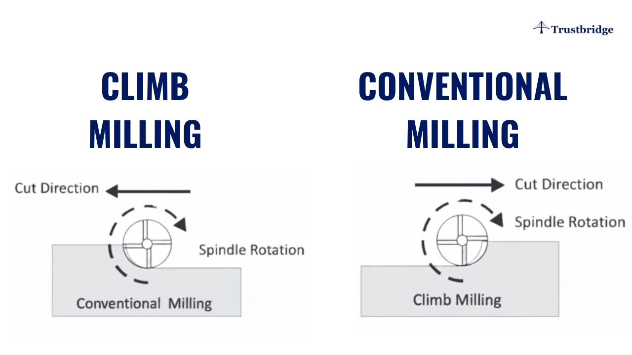
Climb Milling: The Go-To Approach for Cleaner, Faster Machining
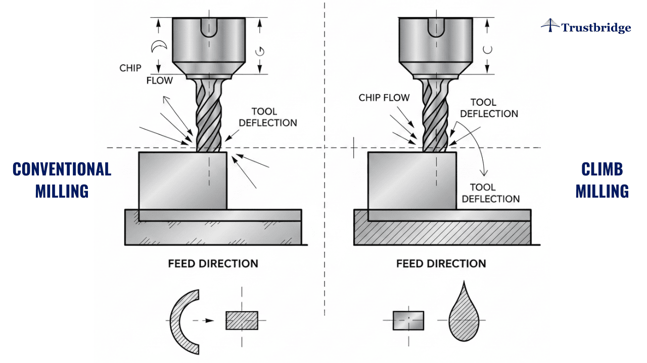
Climb milling lets the cutter rotate with the feed direction, which forms a thick-to-thin chip. This reduces heat, rubbing, and cutting pressure, resulting in a naturally smoother surface finish. Because forces pull the cutter into the workpiece, cutting loads become more predictable and stable, especially on modern CNC machines equipped with rigid spindles and backlash-free motion. For designers working with cosmetic surfaces, fine edges, or long-contour profiles, allowing sufficient access for climb milling gives machinists the freedom to use the most efficient and reliable strategy.
Another advantage is tool life. With less sliding friction, coated end mills maintain sharper cutting edges for longer cycles. This matters especially when your design includes large 3D surfaces, sculpted contours, or precision mating surfaces where repeatability is critical. By giving machinists enough room to control orientation and entry, you encourage the use of optimal chip formation and machining direction.
Example:
A CNC shop machining 6061-T6 aluminum enclosures uses climb milling for the finishing passes. This produces a smoother cosmetic surface, reduces burrs, and extends tool life essential for designer-driven parts with visible faces.
Conventional Milling: The Backup Strategy Designers Should Remember
Conventional milling feeds the tool against rotation, producing a thin-to-thick chip. This generates more friction and heat, which can cause rubbing or chatter on rigid materials. Machinists typically avoid it unless the geometry creates a situation where climb milling becomes unstable particularly with extended overhangs or minimal fixturing area. When your part includes delicate features or insufficient support, the cutting forces in climb milling may pull the part off the fixture, making conventional milling the safer choice.
Designers sometimes unintentionally create conditions where conventional milling is the only option. Features like narrow slots, tall slender walls, or highly directional surfaces may force the cutter to approach from a disadvantageous angle. When this happens, machining slows down, tool wear increases, and surface finish may decline. Understanding this helps designers create geometry that avoids forcing the shop into inefficient toolpath choices.
Example:
When machining hardened steel brackets, a shop uses conventional milling during roughing because it reduces tool pull-in and provides more stability on rigid materials especially when holding conditions are limited.
A Designer Scenario: One Small Geometry Change, Big Manufacturing Impact
Picture a pocket with sharp internal angles, thin walls, and limited cutter entry. The CAM programmer might be forced to switch between climb and conventional milling to avoid chatter or tool deflection—slowing the process and raising cost. But adding a slightly larger fillet radius, reinforcing wall thickness, or opening the tool’s approach path allows full climb milling and delivers cleaner, faster machining.
That’s design for manufacturability done right.
Design Moves That Make Machining Easier (Without Changing Your Vision)
Small geometry choices often determine whether a machinist can maintain consistent tool engagement. Features that incorporate smooth transitions, predictable radii, or softened internal edges create a more controlled machining environment. A simple increase in wall thickness or a more accessible approach angle can dramatically reduce cutter deflection, especially in deeper cavities.
Better geometry also means clearer communication. When your CAD intentionally supports machining access, machinists can evaluate the model without guessing how a feature was intended to be manufactured. That reduces back-and-forth discussions and improves the efficiency of industrial designer–manufacturer collaboration during both prototyping and production. Even cosmetic features benefit from this clarity, as machinists can prioritize climb milling where precision and visual quality matter most.
The CAD–CAM Link Designers Should Leverage Early
Even advanced CAD-CAM software can't fully compensate for geometry that restricts the optimal toolpath. Deep pockets with narrow openings, overhangs with limited approach space, or long unsupported spans can affect cutter deflection and force the programmer to choose slower or suboptimal milling directions. When designers coordinate early with machinists or CAM programmers, tooling decisions become more predictable and prevent costly late-stage redesigns.
This early alignment becomes especially important when prototypes transition into production. A model that works for one-off machining may become too slow or inconsistent for medium- or high-volume manufacturing. By designing with toolpath direction in mind, you reduce hidden costs and support stable prepare CAD for manufacturing workflows.
Trustbridge Tip: Understanding climb milling vs conventional milling helps designers create CNC-friendly geometry—but manufacturability doesn’t stop at machining. As products move from prototypes to production, designers also need to consider how features, wall thicknesses, parting lines, and draft angles impact injection molding. These early decisions reduce redesigns, improve manufacturability across processes, and strengthen collaboration with suppliers. To explore how smart geometry choices improve both machining and molding outcomes, read our guide: Injection Molding Design Guidelines: What Designers Need Know.
Designer Insight: The Simple Access Rule
If a cutter can approach your feature with stability, clearance, and consistent engagement, climb milling is almost always feasible. When geometry blocks access or introduces vibration-prone sections, conventional milling may become necessary even if it is less efficient. Designers can apply a simple mental rule: “How will a tool enter and exit this feature?” This small habit immediately improves manufacturability and reduces surprises during CAM programming.
Just thinking through tool approach, engagement angle, and exit movement can prevent many common machining bottlenecks. This mindset ensures your design supports efficient, predictable, and cost-effective machining without compromising your artistic or functional intent.
Conclusion
Trustbridge supports manufacturers by helping them implement advanced technologies and optimize design-to-manufacturing workflows. Ready to bring your designs to life with immersive technologies? Discover how Trustbridge can support your journey. Visit Trustbridge.pro to explore resources, case studies, and solutions designed for forward-thinking designers and manufacturers.
Frequently Asked Questions
1. What is the main difference between climb milling vs conventional milling?
Climb milling cuts with the tool rotation, producing a smoother finish and reducing tool wear. Conventional milling cuts against rotation, increasing friction and vibration. Understanding this helps designers predict machining outcomes and make better manufacturability decisions.
2. How does climb milling vs conventional milling influence how I prepare CAD for manufacturing?
Cut direction impacts tool access, surface finish, and cutting forces. When preparing CAD for manufacturing, designers should avoid sharp internal corners, add accessible edges, and consider part orientation so machinists can use optimal toolpaths.
3. Does understanding milling direction improve industrial designer–manufacturer collaboration?
Yes. When designers understand how cutting direction affects fixturing, tool reach, and CAM strategy, it reduces design revisions and speeds up quoting—leading to smoother industrial designer–manufacturer collaboration.