
Insert Geometry Decoded: Why the Chip Breaker Matters More Than Grade for CNC Tool Performance
Insert grade often receives most of the attention during tooling selection, but chip breaker geometry frequently has a greater impact on cutting stability, chip control, and machining performance. Different materials behave differently under load, and matching insert geometry to material characteristics is critical for optimizing CNC tool efficiency. In both steel and nonferrous metals machining, incorrect chip breaker selection can increase vibration, poor chip evacuation, and premature tool wear even when insert grade is correct. Understanding how insert geometry influences cutting behavior helps suppliers improve machining consistency, surface finish quality, and overall production efficiency.
Introduction
Selecting a cutting insert is about much more than choosing the correct grade. While insert grades determine characteristics such as wear resistance, coating technology, and temperature capability, the chip breaker geometry has a far greater influence on how the cutting process actually behaves. It controls chip formation, chip evacuation, cutting forces, and ultimately the stability of the machining operation.
Different materials respond very differently during machining. Steel typically requires controlled chip curling to prevent long ribbon chips, aluminum benefits from open geometries that promote free chip flow, and stainless steel often demands aggressive chip control to overcome its tendency to produce stringy chips. Using the wrong geometry can result in poor surface finish, unstable cutting conditions, excessive spindle load, and shortened tool life regardless of how advanced the insert grade may be.
As machining operations become faster and more automated, reliable chip control becomes even more critical. Poor chip evacuation can interrupt production, damage finished components, or even stop an automated machining cell altogether. Selecting the proper chip breaker allows manufacturers to maintain stable cutting conditions while reducing downtime and improving machining consistency.
For every advanced machining supplier, understanding the relationship between insert geometry, workpiece material, feed rate, and machining strategy is essential for maximizing cnc tool performance and building reliable production processes.
How Chip Breakers Actually Work
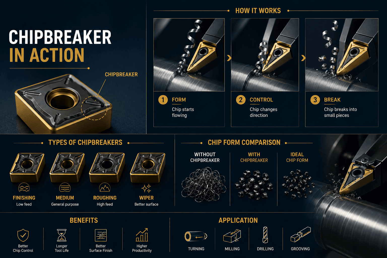
Many machinists know that chip breakers improve chip control, but fewer understand the engineering principles behind them. A chip breaker is not simply a groove machined into an insert—it is a carefully designed geometry that manipulates the chip immediately after it separates from the workpiece. By controlling the chip's direction and curvature, the insert can determine whether chips remain long and dangerous or break into short, manageable pieces.
Understanding how chip breakers function makes it much easier to choose the correct insert geometry for different machining applications. It also explains why the same insert can perform exceptionally well under one set of cutting conditions but poorly under another.
Chip Curling Is What Creates Controlled Chip Breaking
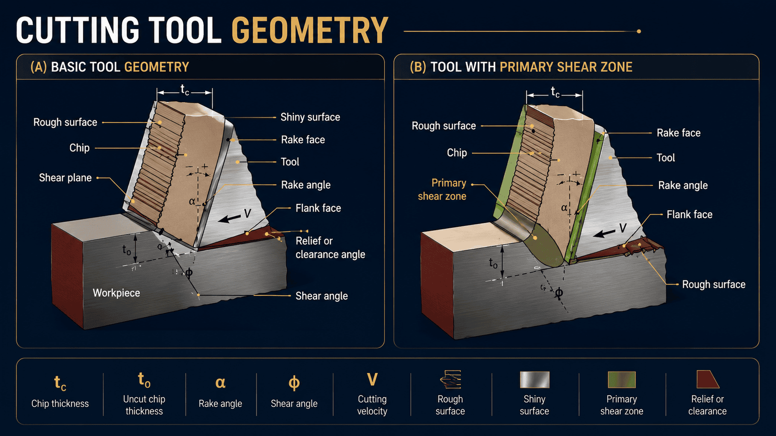
As material is sheared from the workpiece, the chip begins sliding across the rake face of the insert. Instead of moving in a straight path, it encounters the chip breaker geometry, which forces the chip to curl into a tighter radius.
As this curvature increases, internal stresses build within the chip. Once these stresses exceed the material's strength, the chip fractures into smaller, controlled segments that evacuate efficiently from the cutting zone.
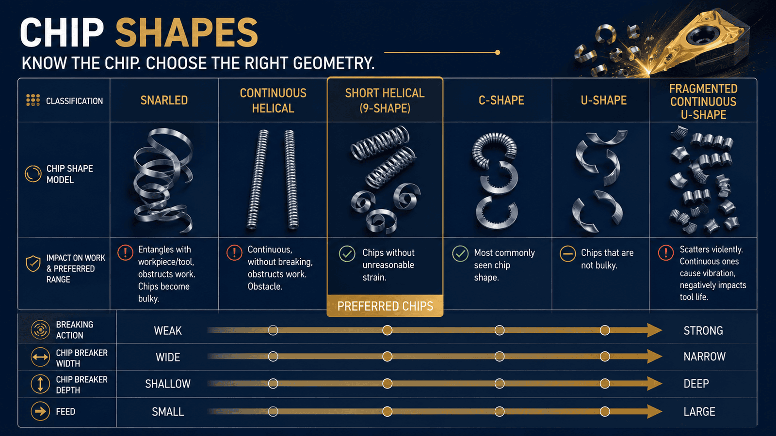
If the chip never curls enough because the feed rate is too low or the geometry is unsuitable, it remains as a long ribbon that wraps around the tool or workpiece. Conversely, if the chip curls too aggressively under heavy cutting loads, cutting forces increase unnecessarily and may accelerate insert wear or cause vibration.
Why Good Chip Control Matters Beyond Housekeeping
Many operators think chip breakers simply make the machine easier to clean. In reality, proper chip control has a direct impact on machining quality, productivity, and workplace safety.
Long continuous chips can scratch finished surfaces, wrap around rotating tools, clog chip conveyors, interfere with automatic tool changers, and even stop robotic production systems. They also create safety hazards for operators who may need to remove tangled chips manually.
Well-controlled chips evacuate consistently, carry heat away from the cutting zone, reduce recutting, and allow the machining process to remain stable during long production runs. Better chip control ultimately contributes to improved surface finish, longer tool life, and more predictable machining performance.
Why Feed Rate and Depth of Cut Matter
One of the biggest misconceptions in machining is that a chip breaker will perform the same way regardless of the cutting conditions. In reality, every chip breaker is designed to operate within a specific window of feed rates and depths of cut. When machining parameters fall outside this operating range, chip control quickly begins to deteriorate.
This explains why two shops using the same insert may experience completely different results. Often, the insert itself is not the problem—the machining parameters simply do not allow the chip breaker to function as intended.
Understanding how feed rate and depth of cut influence chip formation helps programmers avoid many common tooling problems before they occur.
Feed Rate Controls Chip Formation
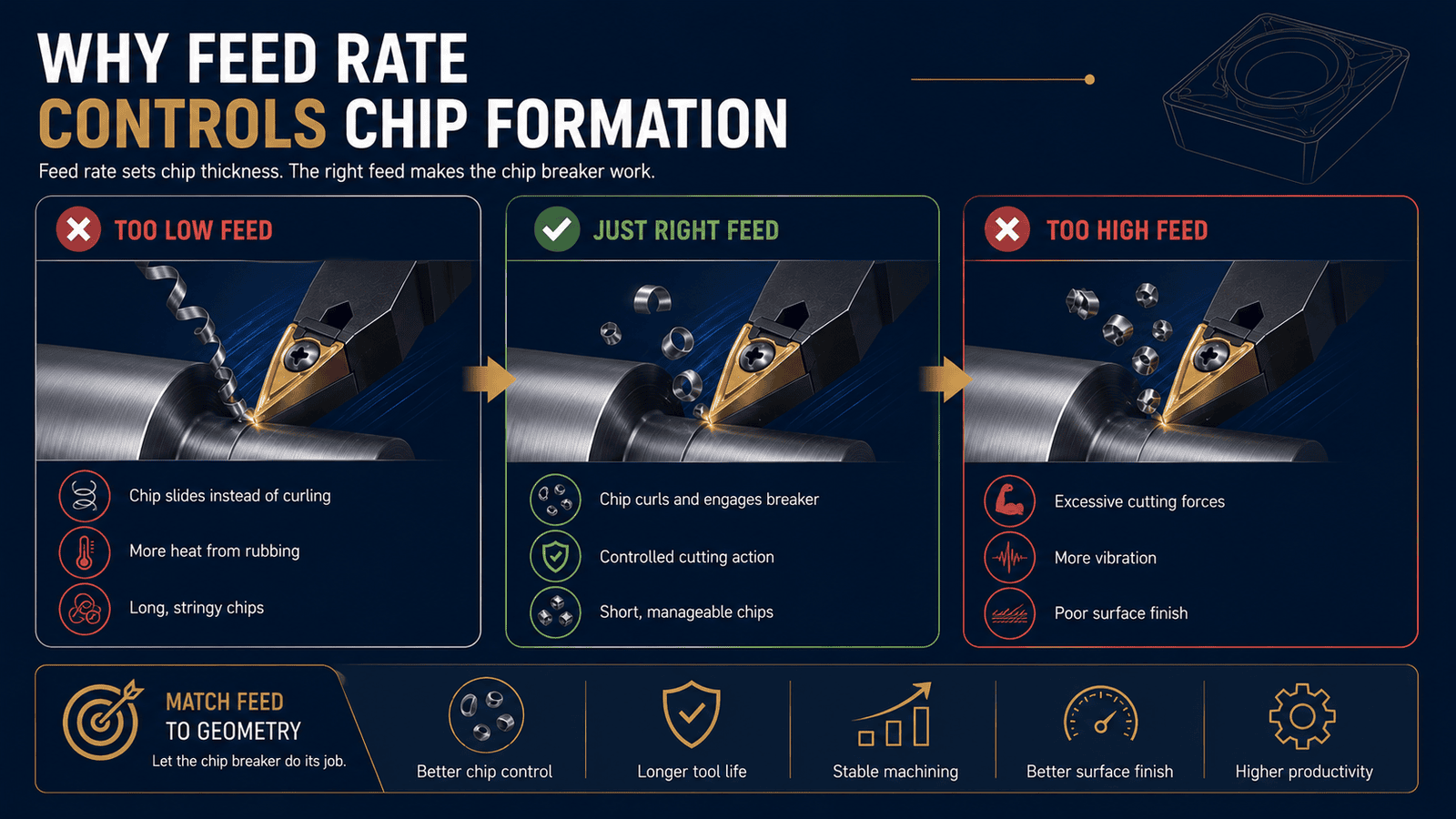
Feed rate determines chip thickness, which directly affects whether the chip breaker can engage properly.
When the feed rate is too low, the chip may slide across the insert without entering the chip breaker groove. Instead of curling and fracturing, it forms long stringy chips while generating unnecessary heat through rubbing rather than efficient cutting.
Some shops mistakenly reduce feed rates to extend insert life. Ironically, this often produces the opposite result because the insert spends more time rubbing against the material, increasing friction, built-up edge, and premature wear.
On the other hand, excessively high feed rates overload the chip breaker geometry, increasing cutting forces, spindle load, and machine vibration. Staying within the manufacturer's recommended feed range allows the insert to perform as designed.
Depth of Cut Must Match the Geometry
Depth of cut has just as much influence on chip formation as feed rate.
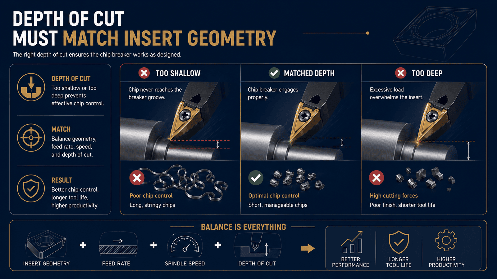
Light finishing geometries are engineered for shallow cuts and lower cutting forces, while heavy roughing geometries require greater material engagement before the chip breaker begins functioning efficiently.
Using a heavy-duty roughing insert for light finishing often results in poor chip control because the chip never reaches the groove intended to curl and fracture it. Likewise, using a finishing geometry during aggressive roughing can overload the cutting edge, reducing insert life and compromising machining stability.
Matching both feed rate and depth of cut to the intended chip breaker geometry produces more consistent chip evacuation, lower cutting forces, and better machining performance.
Selecting the Right Chip Breaker for Different CNC Machining Materials
Every material behaves differently under the cutting tool. Differences in hardness, ductility, thermal conductivity, and work-hardening characteristics all influence how chips form and how the insert should manage them. For this reason, selecting the correct chip breaker always starts with understanding the material being machined.
However, material selection alone is not enough. Machine rigidity, spindle power, coolant delivery, and the machining operation itself also influence which geometry will provide the most stable results. Experienced machinists evaluate the complete machining system rather than selecting inserts solely from a catalog.
Steel, Stainless Steel, and Cast Iron Require Different Chip Breaker Designs
Although these materials are often grouped together, their machining behavior varies significantly. Carbon and alloy steels generally produce long continuous chips that require controlled chip curling and fracture. Medium or roughing chip breaker geometries typically provide excellent chip control while maintaining stable cutting forces across a wide operating range.
Stainless steels present greater challenges because they are highly ductile and tend to work harden during machining. They often generate long, tough chips that resist breaking naturally. More aggressive chip breaker geometries help force tighter chip curling, improving chip evacuation while reducing the risk of bird-nesting around the tool.
Cast iron behaves very differently. Because it is naturally brittle, it produces small fragmented chips with minimal assistance. Chip breaker selection therefore focuses less on aggressive chip control and more on maintaining edge strength and resisting abrasive wear during long production runs. Understanding these differences helps programmers improve chip evacuation while maintaining stable cutting conditions across a variety of ferrous materials.
Nonferrous Metals Need Free Chip Flow Instead of Aggressive Chip Breaking
Materials such as aluminum, brass, and copper require a completely different machining approach. These metals are softer, more ductile, and highly susceptible to built-up edge. Instead of breaking naturally, they often produce long continuous chips that can wrap around the cutter if chip flow is restricted. For these applications, insert geometries typically feature polished rake faces, positive cutting angles, and open chip channels that encourage chips to flow freely away from the cutting edge. Rather than aggressively breaking the chip, these geometries minimize friction and reduce material adhesion to the insert.
Using a steel-oriented chip breaker on aluminum frequently results in built-up edge, poor surface finish, increased spindle load, and inconsistent machining performance. Selecting an open geometry specifically designed for nonferrous materials improves dimensional accuracy while allowing higher cutting speeds and smoother chip evacuation.
Even when using inserts specifically designed for aluminum, programmers should still verify that feed rate, cutting speed, and machining strategy align with the geometry's intended operating window to achieve the best possible results.
Common Chip Breaker Selection Mistakes
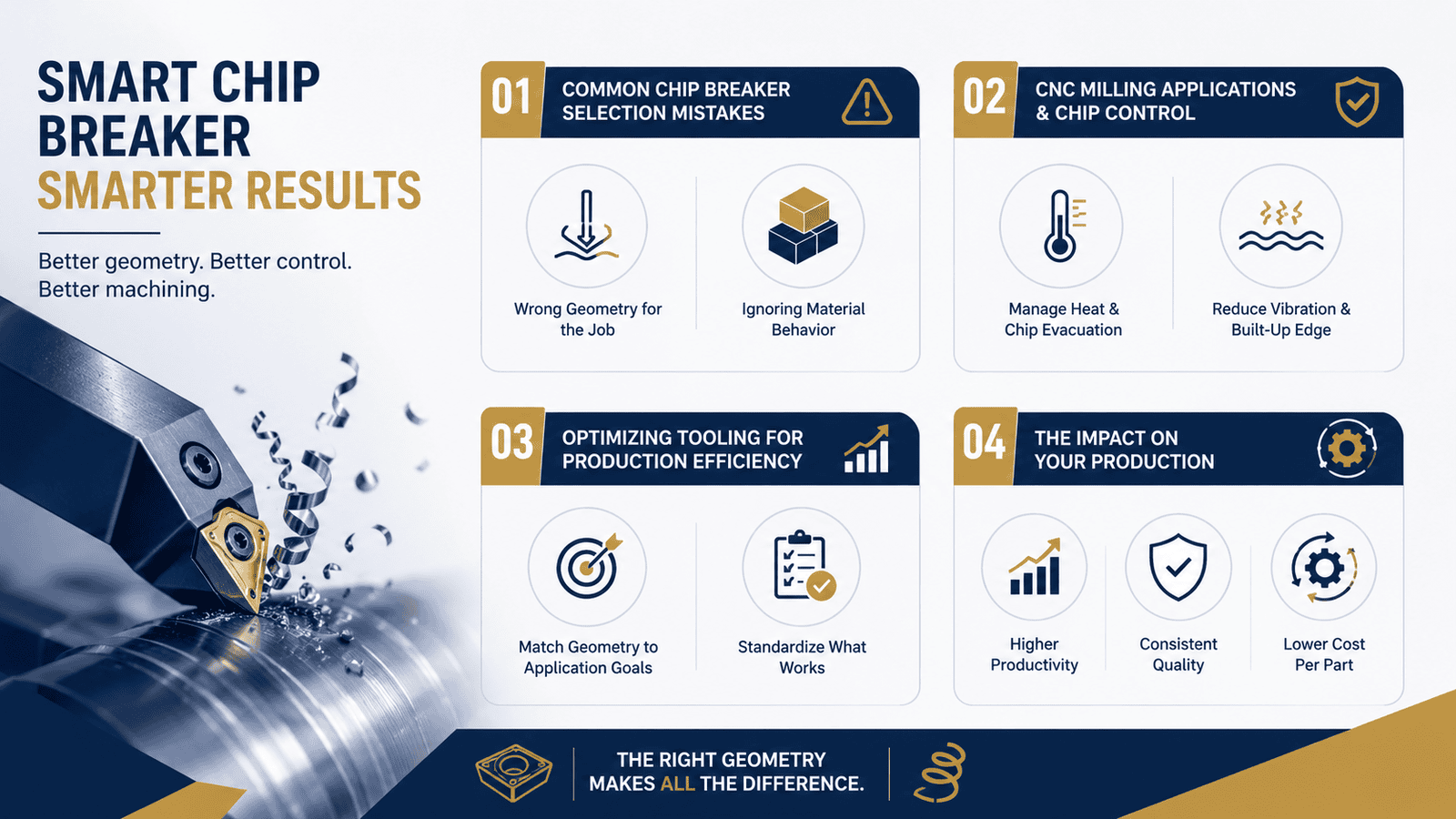
Many machining problems begin long before the insert touches the workpiece. In many cases, poor machining performance is caused not by the machine or the insert itself, but by selecting a chip breaker that does not match the application. Shops often rely on habit, previous experience, or catalog recommendations without fully considering the material, machining operation, or cutting conditions.
Recognizing these common mistakes helps suppliers reduce tooling costs, improve chip control, and achieve more stable cnc tool performance across different production environments.
Selecting Geometry Based Only on Insert Grade
One of the biggest misconceptions in machining is assuming that a premium insert grade will automatically deliver better cutting performance.
In reality, insert grades primarily determine wear resistance, coating characteristics, and temperature capability. They do not control how chips curl, fracture, or evacuate from the cutting zone. Those functions are determined by the chip breaker geometry.
An expensive insert with the wrong geometry may perform far worse than a standard insert whose chip breaker is designed specifically for the material and machining operation. Successful insert selection should therefore begin with choosing the correct geometry before evaluating insert grades or coatings.
Ignoring the Actual Machining Operation
Many suppliers choose inserts based only on the workpiece material while overlooking the demands of the machining operation itself.
A roughing operation requires an insert capable of handling high feed rates, deeper cuts, and larger chip loads. Finishing operations, on the other hand, prioritize lower cutting forces, improved surface finish, and dimensional accuracy. Interrupted cuts also require stronger cutting edges than continuous machining because of repeated impact loading.
Machine rigidity, spindle power, coolant delivery, workholding stability, and toolpath strategy also influence insert performance. Evaluating the complete machining process instead of focusing only on the material leads to more reliable chip control, improved tool life, and fewer production interruptions.
Conclusion
Selecting the right chip breaker involves much more than choosing an insert from a tooling catalog. While insert grades determine wear characteristics and temperature resistance, the chip breaker geometry controls how material is removed, how chips behave, and how efficiently the machining process operates.
Every workpiece material generates chips differently. Steel typically requires controlled chip curling, stainless steel demands aggressive chip control to manage work-hardening behavior, while aluminum and other nonferrous metals benefit from open geometries that encourage smooth chip flow. Feed rate and depth of cut are equally important because every chip breaker is engineered to operate within a specific cutting window.
By understanding how insert geometry interacts with cnc machine and programming strategies, machining suppliers can improve chip evacuation, reduce vibration, extend tool life, enhance surface finish, and build more stable production processes. Choosing the correct chip breaker is one of the simplest ways to improve cnc tool performance without making major investments in new equipment.
Selecting the right insert geometry is only one part of achieving consistent machining performance. Long-term success also depends on effective programming strategies, machine capability, tooling selection, and process optimization working together as a complete manufacturing system.
At Vulcury, we help manufacturing businesses solve real production challenges by providing practical engineering insights that improve machining efficiency—not just tooling recommendations. Our supplier-focused resources help teams optimize cnc machine and programming workflows, improve cnc tool performance, reduce production risk, and make more informed manufacturing decisions.
Whether you're refining chip control across different materials, improving tooling strategies, or optimizing machining consistency for high-volume production, Vulcury provides the technical knowledge needed to build smarter, more reliable manufacturing operations.
Explore more supplier-focused engineering insights from Vulcury to discover practical strategies for improving machining performance, reducing tooling costs, and building more competitive CNC manufacturing processes.
Frequently Asked Questions
1. What is a chip breaker, and why is it important in CNC machining?
A chip breaker is a specially designed geometry on a cutting insert that controls how chips curl, fracture, and evacuate during machining. Choosing the correct chip breaker improves chip control, reduces cutting forces, enhances cnc tool performance, extends tool life, and helps maintain stable machining conditions across different materials.
2. How do you choose the right chip breaker for different CNC machining materials?
The right chip breaker depends on the workpiece material, machining operation, feed rate, and depth of cut. Steel generally requires controlled chip-breaking geometries, stainless steel benefits from more aggressive chip control, while aluminum and other nonferrous metals perform best with open, polished geometries that promote smooth chip flow and minimize built-up edge.
3. How do feed rate and depth of cut affect chip breaker performance?
Every chip breaker is designed to operate within a specific cutting range. If the feed rate is too low, chips may not curl properly and can become long and stringy. If the feed or depth of cut is too high, cutting forces increase, leading to vibration, excessive insert wear, and unstable machining. Matching machining parameters to the insert geometry is essential for consistent cnc tool performance.
4. What are the most common chip breaker selection mistakes in CNC machining?
The most common mistakes include selecting inserts based only on insert grade, ignoring the machining operation, and failing to match chip breaker geometry to the material and cutting conditions. Successful cnc machine and programming strategies consider the complete machining system including material behavior, machine rigidity, tooling, coolant delivery, and machining parameters—to achieve reliable chip control and stable production.