
Teflon (PTFE) Material Explained: Design for Manufacturing Decisions Designers Must Get Right
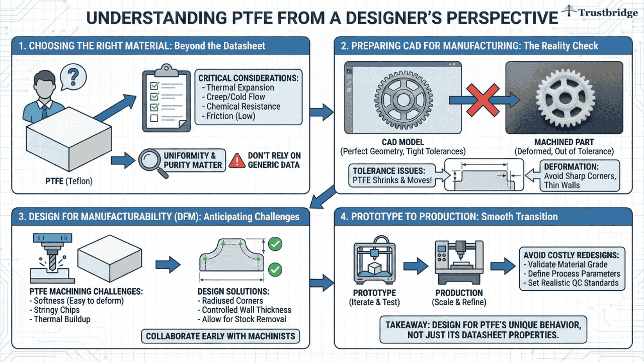
Choosing the right material is one of the most critical decisions a designer makes, especially for precision parts. Many teams have experienced the frustration of PTFE parts that look perfect in CAD but fail to fit, deform, or drift once machined or assembled.
This is where design for manufacturing becomes essential. PTFE behaves very differently from metals and rigid plastics, and those differences directly affect geometry, tolerances, and long-term performance. What appears acceptable on a datasheet can introduce real-world challenges during machining and production.
This blog explains PTFE entirely from a designer’s perspective, focusing on material selection in product design, how to prepare CAD for manufacturing, and how to move smoothly from prototype to production without costly redesign cycles.
Understanding PTFE from a Designer’s Perspective
Choosing the right material is one of the most critical decisions a designer makes, especially when working on precision parts material selection. Many teams have experienced the frustration of PTFE parts that look perfect in CAD but fail to fit, deform, or drift once machined or assembled.
This is where design for manufacturability becomes essential. PTFE behaves very differently from metals and rigid plastics, and those differences directly affect geometry, tolerances, and long-term performance. What appears acceptable on a datasheet can introduce real PTFE machining challenges during production
This blog explains PTFE entirely from a designer’s perspective, focusing on material selection in product design, how to prepare CAD for manufacturing, and how to move smoothly from prototype to production without costly redesign cycles.
Why Designers Choose PTFE for Precision Parts
Designers do not choose PTFE for aesthetics or ease of manufacturing. They choose it because no other material performs quite the same way in specific conditions. PTFE excels when parts must slide repeatedly without lubrication, resist aggressive chemicals, or operate across wide temperature ranges.
From a design standpoint, PTFE often appears in components that interact directly with other parts. Bushings, wear pads, valve seats, and guides rely on PTFE’s self-lubricating properties to reduce wear and noise. In these applications, the designer’s responsibility goes beyond selecting the material. The surrounding geometry must support PTFE’s softness while preventing creep, deformation, or premature failure.
Understanding these trade-offs is a core part of precision parts material selection and long-term product reliability.
Design for Manufacturing with PTFE: What Designers Must Anticipate
PTFE is rarely injection molded for precision parts. Most PTFE components are machined from sintered billets, which immediately affects how designers should approach design for manufacturing.
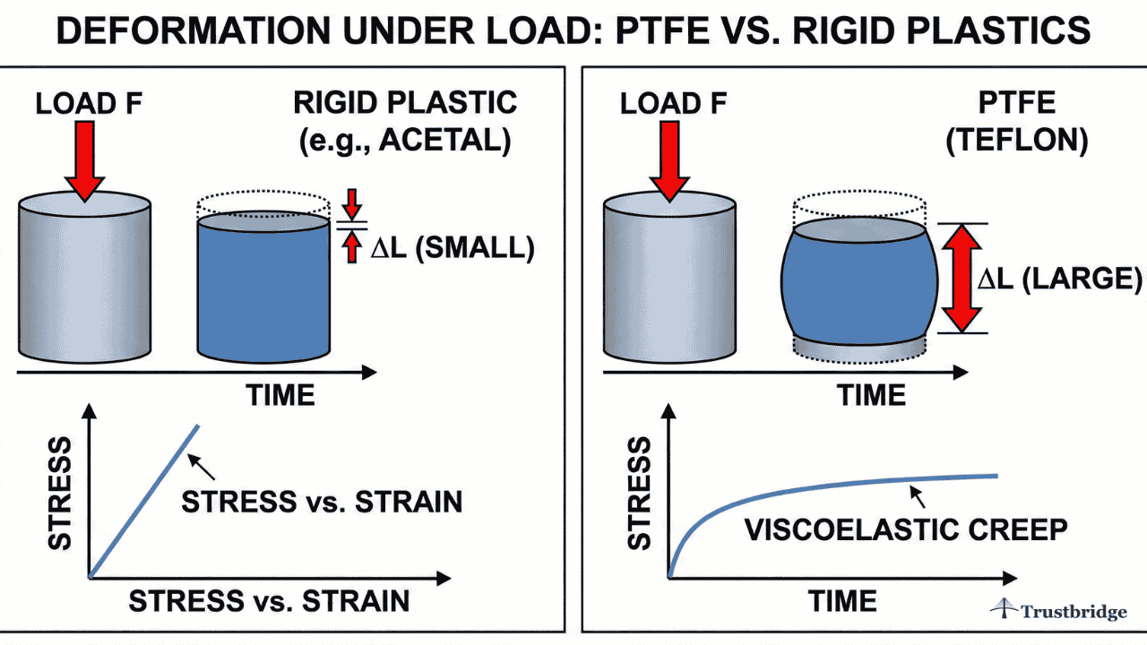
PTFE machines differently than rigid plastics. It tends to deflect under cutting forces, does not hold sharp edges well, and can relax after machining. Designers who specify ultra-tight tolerances without understanding these PTFE machining challenges often encounter fit issues once parts leave the machine.
PTFE Geometry and Dimensional Stability
From a CAD perspective, PTFE parts should avoid thin walls, long unsupported features, and sharp internal corners. These geometries amplify deformation and make tolerance control difficult. Designers who account for PTFE’s flexibility early create parts that perform consistently rather than unpredictably.
This is where prepare CAD for manufacturing becomes critical. CAD that looks correct on screen may not reflect how PTFE behaves after machining, cooling, and assembly.
Trustbridge Tip: Choosing PTFE for precision parts is a smart design decision—but long-term manufacturing success depends on how well designers account for downstream production realities. Even when PTFE parts are machined rather than molded, many failures stem from ignoring foundational molding principles like uniform wall thickness, draft intent, and flow-friendly geometry. These same principles reduce distortion, tolerance drift, and rework across materials. To understand how applying injection-molding design guidelines early can strengthen your overall design for manufacturing approach, read our blog: Injection Molding Design Guidelines: What Designers Need to Know.
Preparing CAD for Manufacturing When Using PTFE
Designers often assume that if a part can be modeled, it can be manufactured exactly as drawn. PTFE challenges that assumption. Preparing CAD for PTFE requires designers to think beyond nominal dimensions and consider how the material will behave during and after machining.
Tolerance Strategy for PTFE Parts
PTFE does not behave like metal. It compresses, relaxes, and responds to load over time. Designers should avoid blanket tight tolerances and instead define functional tolerances only where necessary. Press fits, sliding interfaces, and sealing surfaces require special attention, while non-critical dimensions should remain flexible.
Clear communication in CAD drawings helps manufacturers understand intent, strengthening industrial designer manufacturer collaboration and reducing unnecessary back-and-forth.
Surface Finish and Edge Design
Sharp edges in PTFE are fragile and often degrade during use. Designers should intentionally soften edges and transitions in CAD to reflect real-world performance. Surface finish expectations should also be realistic, as PTFE does not polish the same way as harder plastics or metals.
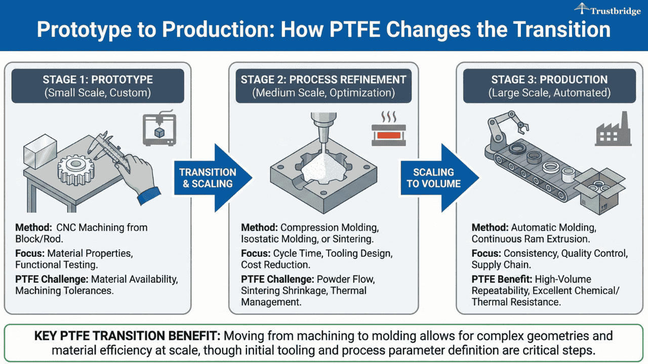
Prototype to Production: How PTFE Changes the Transition
PTFE is often introduced during prototyping when designers are testing friction, wear, or chemical exposure. However, what works in a prototype does not always translate cleanly into production.
During early prototypes, parts may be machined slowly with generous allowances. As production volumes increase, machining strategies change, tooling wear increases, and cycle times become important. Designers who anticipate this shift create geometries that scale smoothly from prototype to production.
This transition is where many PTFE projects fail not due to material choice, but due to insufficient manufacturing foresight during design.
Why Industrial Designer–Manufacturer Collaboration Is Essential for PTFE
PTFE is often introduced during prototyping when designers are testing friction, wear, or chemical exposure. However, what works in a prototype does not always translate cleanly into production.
During early prototypes, parts may be machined slowly with generous allowances. As production volumes increase, machining strategies change, tooling wear increases, and cycle times become important. Designers who anticipate this shift create geometries that scale smoothly from prototype to production.
This transition is where many PTFE projects fail not due to material choice, but due to insufficient manufacturing foresight during design.
Design for Manufacturability as a Creative Advantage
Some designers worry that design for manufacturability limits creativity. In reality, the opposite is true, especially with PTFE. Designers who understand material constraints gain more control, not less.
When designers account for PTFE’s softness, deformation, and machining limits, they create parts that last longer, assemble more reliably, and perform better in real-world conditions. Manufacturability becomes a design tool rather than a restriction.
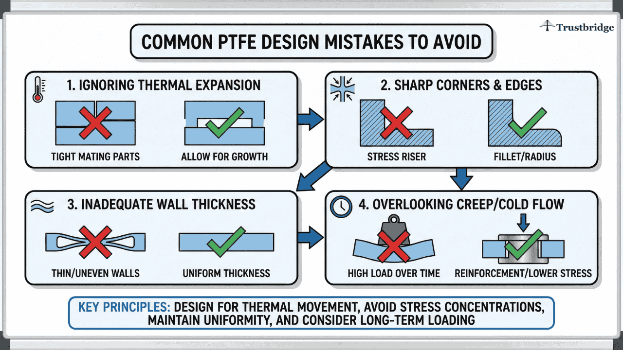
Common PTFE Design Mistakes Designers Should Avoid
Many PTFE-related failures trace back to early design decisions. Overly thin sections, unnecessary tight tolerances, sharp internal corners, and unsupported features often lead to creep, distortion, or inconsistent fit.
Designers who treat PTFE like a rigid plastic set themselves up for redesign cycles. Designers who treat PTFE as a responsive material build parts that succeed in production.
Conclusion: Using PTFE Successfully Through Design for Manufacturing
Teflon is a powerful material, but only when designers respect how it behaves beyond the CAD screen. Choosing PTFE is not just a material decision—it is a commitment to thoughtful design for manufacturing, careful precision parts material selection, and strong collaboration with manufacturers.
Designers who know how to prepare CAD for manufacturing, plan the shift from prototype to production, and work closely through industrial designer manufacturer collaboration create PTFE parts that perform reliably, scale smoothly, and avoid costly surprises.
When used intentionally, PTFE becomes more than a solution it becomes a competitive design advantage.Visit Trustbridge.pro to explore resources, case studies, and solutions designed for forward-thinking designers and manufacturers.
Frequently Asked Questions (FAQs)
1. Why do PTFE parts often fail to meet tolerances even when the CAD model looks correct?
PTFE behaves very differently from metals and rigid plastics. During machining, it can deflect under cutting forces and then relax after the operation is complete. This means a part that measures correctly on the machine may drift out of tolerance once it cools or is removed from fixturing. Designers who don’t account for this behavior during design for manufacturing often see fit and assembly issues later.
2. What are the biggest PTFE machining challenges designers should anticipate early?
The most common PTFE machining challenges include material softness, poor edge definition, dimensional relaxation, and sensitivity to cutting pressure. These factors make sharp corners, thin walls, and ultra-tight tolerances risky. Designers who consider these challenges while they prepare CAD for manufacturing reduce rework and improve production consistency.
3. How should designers approach tolerances for PTFE precision parts?
PTFE should not be toleranced like metal. Instead of applying tight tolerances everywhere, designers should define functional tolerances only where performance depends on them, such as sealing or sliding interfaces. Looser tolerances on non-critical features allow manufacturers to machine PTFE more reliably and consistently, improving yield during production.