
Why Parts Fail First Article Inspection and How Better Design Prevents It with a CAD Preparation Checklist
Parts often fail First Article Inspection (FAI) because the CAD model and manufacturing documentation do not clearly communicate how the part should be manufactured and inspected. Incomplete drawings, poorly defined datums, unrealistic tolerances, revision mismatches, and missing inspection details can all lead to non-conformances, even when the part is machined correctly. Preparing CAD models and drawings for manufacturing with FAI in mind helps engineering teams identify these issues early, reduce costly rework, and improve the transition from prototype to production.
Introduction
A failed first article inspection usually gets filed as a supplier problem. The FAIR comes back with a rejected characteristic, someone asks the shop what happened, and the shop opens a corrective action. That's the visible part of the story, and it's usually not the true starting point.
Look upstream on enough failed FAIRs and a pattern shows up: the part that failed was often built exactly as drawn. What failed wasn't the machinist's ability to hit a number it was the drawing's ability to say, unambiguously, what that number needed to be, relative to what, and how anyone was supposed to check it. Preparing CAD for manufacturing isn't just about geometry a machine can physically cut. It's about producing a drawing and model that someone else on a coordinate measuring machine, in a different building can verify exactly the way an engineer imagined it. This piece walks through where that breaks down, and closes with a CAD preparation checklist worth running before any drawing goes out.
Why parts fail FAI more often than shops expect
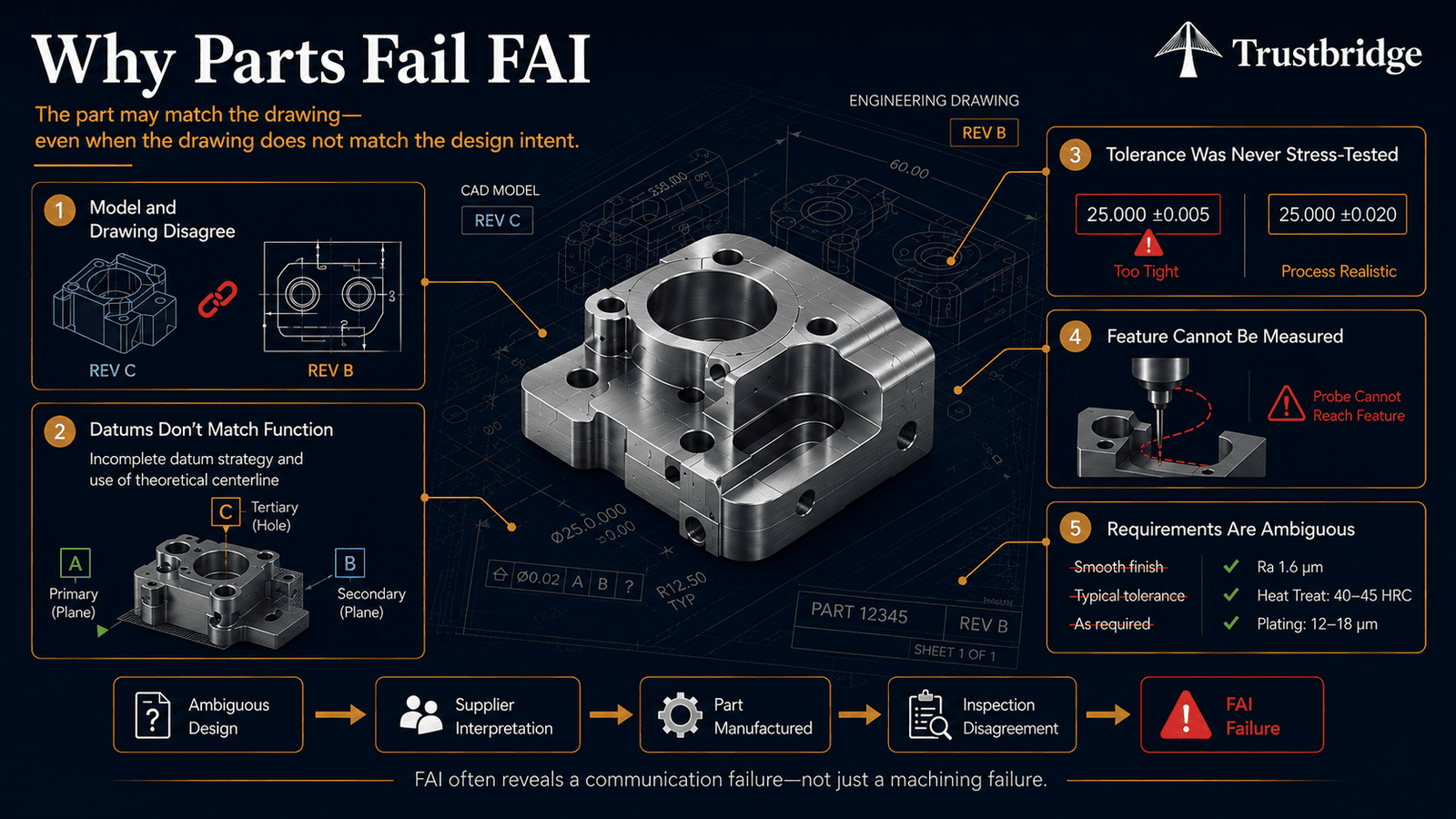
It's tempting to assume a failed first article means a shop cut something wrong. Sometimes that's true. More often, the part matches what the drawing said the drawing just didn't say what the designer meant. Manufacturing-engineering resource Modus Advanced puts it plainly: the most common failure mode isn't a supplier ignoring a tolerance, it's a supplier interpreting that tolerance differently than the designer intended.
That distinction matters: a machining problem gets fixed on the shop floor; an interpretation problem gets fixed at a keyboard, before the drawing is ever released and it's a lot cheaper to fix there. According to engineering-drawing reference Jiga, ambiguous drawing annotation, not poor machining, is the most common source of tolerance disputes between buyers and suppliers exactly the kind of dispute a first article inspection is designed to surface. None of this is a knock on designers. It's a reminder that a drawing is a communication tool first and a geometry file second, and communication tools fail quietly until someone downstream has to guess.
The design-side reasons parts fail FAI
A handful of patterns account for most of the design-side failures quality teams see repeatedly. None of them require sloppy engineering they're easy to miss precisely because the CAD model itself can look complete while the documentation around it doesn't.
The drawing and the model don't agree
Modern design work happens almost entirely in the 3D model, and it's easy to assume the model tells the whole story. It doesn't. HPPI's engineering blog makes the point directly: a 3D model communicates dimensions, tolerances, material, finish, and critical-to-quality callouts far less completely than an actual annotated drawing a coordinate measuring machine operator still needs datums and tolerances laid out on a print to verify compliance, and a model alone routinely leaves that operator guessing. When a model gets revised late in a project and the drawing isn't regenerated to match, or a drawing is quietly hand-edited without a corresponding model update, the part that gets built and the part that gets ballooned for inspection are no longer the same part on paper. That mismatch doesn't surface until FAI, the first time anyone is required to check the two against each other line by line.
Datums that don't reflect how the part is measured or used
Quality Magazine's reviewers put it well: a datum is supposed to represent how a part actually mounts, assembles, or functions not whichever surface happens to be easiest to measure. When datums get chosen for convenience over function, or a datum reference frame is left incomplete, a part can be dimensionally fine and still fail, simply because the fixture and the function don't agree on what "aligned" means. A specific version of this shows up constantly: a designer references a centerline or another theoretical, constructed feature as a datum. A CMM can measure the part accurately because there are sufficient physical surfaces to probe. However, a theoretical centerline does not provide guidance on how the part was intended to be fixtured. As a result, setups often become assumptions rather than following a clearly defined and documented method.
Tolerances that were never stress-tested past the prototype
A tolerance that worked on a hand-built prototype often isn't the same tolerance a repeatable production process can hold, especially once someone was quietly sanding, shimming, or adjusting parts to get them to assemble. Those adjustments never make it onto the drawing, so the drawing keeps describing a part that only ever existed with a person's hands involved. It's an easy trap to fall into precisely because the prototype worked — proof that a design functions quietly gets mistaken for proof that it can be manufactured, and those are two different claims. First articles are exactly where that gap gets exposed, because a first article has to pass on the strength of the drawing and the process alone, with no one standing by to nudge a feature into place.
Why the coordinate measuring machine doesn't care how good your CAD model looks
A coordinate measuring machine is unforgiving in a specific, useful way: it can't measure anything it hasn't explicitly been told to inspect, no matter how obviously important a surface looked in the CAD viewport. It follows a program built from the drawing's datums, tolerances, and feature callouts, and if those aren't complete, tangible, and physically reachable, the inspection stalls or gets improvised which is exactly what turns a borderline part into a documented FAI failure.
Physical access is a real constraint, not a formality. Probe length, deflection, and approach angle all limit what a CMM can actually reach, particularly on internal or recessed features, as CMM programming specialists at Clarwe point out a beautifully toleranced pocket that a probe genuinely cannot get into is a design problem wearing an inspection costume. This is the deeper version of design for manufacturability: not just whether a mill or a mold can produce a feature, but whether anyone can independently verify it afterward. A design that's manufacturable but not verifiable will still stall at first article inspection, just later in the process, and after more money has already been spent building it.
A CAD preparation checklist before you release the drawing
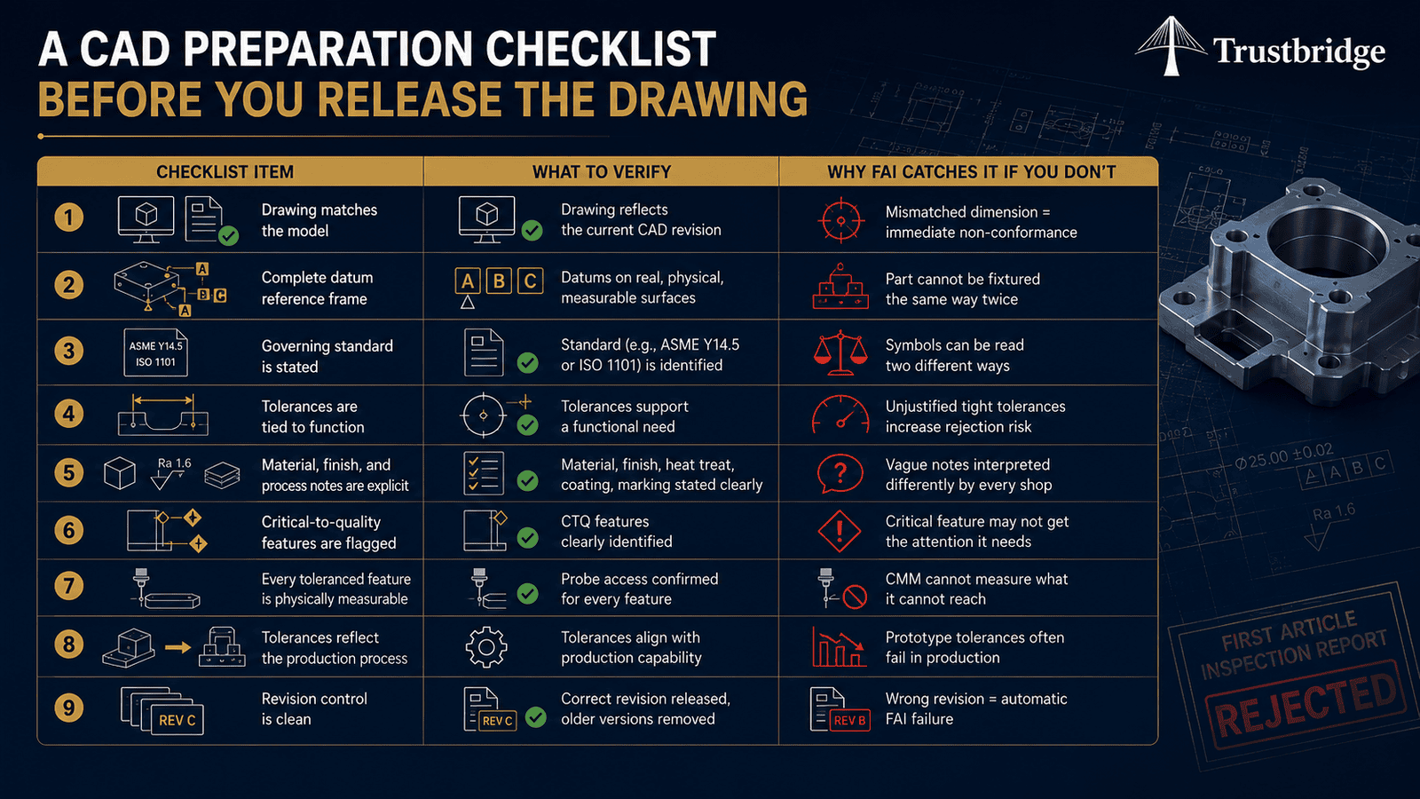
Most of what causes FAI failures shows up on a drawing before it ever reaches a shop, which means most of it is catchable in a five-minute review. The checklist below isn't exhaustive DFM guidance it's aimed specifically at what makes a design fail first article inspection, checked before release instead of discovered after.
Checklist Item | What to Verify | Why FAI Catches It If You Don't |
Drawing matches the model | The released drawing reflects the current CAD revision, not an earlier one | A ballooned dimension that doesn't match the model creates an immediate, avoidable non-conformance |
Complete datum reference frame | Primary, secondary, and tertiary datums are called out on real, physical, measurable surfaces — not theoretical constructs like a centerline | An incomplete or intangible datum makes the part impossible to fixture the same way twice |
Governing standard is stated | The drawing states which tolerancing standard applies (e.g., ASME Y14.5 or ISO 1101) | Without it, a supplier and an inspector can read the identical symbol two different ways |
Tolerances are tied to function | Every tight tolerance sits on a feature that genuinely needs it, not one copied from a template | Unjustified tight tolerances raise rejection risk without buying any real performance |
Material, finish, and process notes are explicit | Surface finish (Ra/Rz), heat treat, plating thickness, and marking requirements are stated as values, not adjectives like "smooth" | A vague note gets interpreted a different way by every shop that reads it |
Critical-to-quality features are flagged | The handful of dimensions that actually drive fit, form, or function are marked distinctly from the rest | An unflagged critical feature may not get the attention it actually needs |
Every toleranced feature is physically measurable | Tight-tolerance features are checked for probe access, not just modeled in isolation | A CMM cannot measure a feature it cannot physically reach, no matter how correct the callout is |
Tolerances reflect the production process | Dimensions are checked against the process that will actually build the part at volume, not what a hand-fit prototype achieved | Prototype-only tolerances are a common reason production runs fail where the prototype quietly passed |
Revision control is clean | The drawing carries a clear revision block, and superseded versions are out of circulation | A supplier building to the wrong revision fails FAI by definition, independent of part quality |
Why this matters even more at the prototype-to-production transition
A working prototype proves a design can function. It doesn't prove the design can be manufactured reliably, repeatedly, and at the tolerances a first article inspection will actually check. The shift that has to happen on the way from prototype to production is a shift from prototype-achieved tolerances to process-based tolerances — using a recognized general tolerancing standard as the reference point for anything that isn't functionally critical, rather than whatever a one-off unit happened to measure after some hand-fitting.
This is also exactly where FAI tends to get treated as an afterthought instead of a planned step. A clean handoff from prototype to production generally depends on complete documentation, a DFM review confirming every geometry and tolerance is genuinely producible at volume, and a defined first article inspection plan agreed on before tooling is committed — not assembled after a surprise rejection. Skipping that planning doesn't remove the risk sitting in the design. It just delays discovering it until tooling, material, and schedule are already committed — the most expensive possible moment to learn a tolerance never really worked outside the prototype shop.
Conclusion
Parts don't usually fail first article inspection because a shop couldn't cut a feature. They fail because a drawing and a model quietly disagreed, a datum didn't reflect how the part was actually going to be measured, or a tolerance that worked once, by hand, was never checked against the process meant to reproduce it at scale. Every one of those causes is visible and fixable before a drawing is ever released — which is the entire argument for treating CAD preparation as part of designing the part, not a formality that happens after the real design work is done.
Want a second set of eyes on your next drawing before it goes to FAI?
Send the drawing and model together, and get a straight read on whether the datums, tolerances, and notes are complete enough to pass a first article inspection on the first try before it costs you a failed FAIR and a rebuild.
Frequently Asked Questions
1. What are the most common CAD preparation mistakes that cause First Article Inspection (FAI) failures?
The most common CAD preparation mistakes include incomplete or outdated drawings, mismatched CAD models and revisions, poorly defined datums, unrealistic tolerances, missing material or surface finish specifications, and incomplete inspection callouts. These issues can cause parts to fail First Article Inspection even when they are manufactured exactly as designed.
2. Why do parts fail First Article Inspection even when they are machined correctly?
Many FAI failures occur because the design documentation is ambiguous rather than because of machining errors. If drawings, tolerances, datums, or revision information do not clearly communicate the design intent, suppliers and inspectors may interpret requirements differently, resulting in non-conformances during inspection.
3. How can engineers prepare CAD models and drawings to improve FAI success?
Engineers can improve FAI success by ensuring the CAD model and drawing match the latest revision, defining complete and measurable datum reference frames, applying only functionally necessary tolerances, specifying materials and surface finishes clearly, and verifying that all critical features can be inspected using standard metrology equipment such as a coordinate measuring machine (CMM).
4. Why is a CAD preparation checklist important before releasing a drawing for manufacturing?
A CAD preparation checklist helps identify documentation issues before production begins. Verifying revision control, tolerances, datums, inspection requirements, and manufacturability early reduces rework, shortens approval cycles, improves communication between design and manufacturing teams, and increases the likelihood of passing First Article Inspection on the first submission.