Metal Casting vs. Sheet Metal Fabrication: Choosing a Process
Choosing between metal casting services and sheet metal fabrication services depends on more than the shape of a part. The right process is determined by factors such as geometry, production volume, structural requirements, tooling costs, lead times, and material performance. Understanding how these trade-offs affect manufacturability, cost, and scalability helps engineering teams select the most suitable process, reduce development risk, and avoid expensive production mistakes.
Introduction
Geometry Complexity, Volume, and Structural Needs Drive the Fork
These three factors are usually the first filter worth applying, well before cost enters the conversation, because together they determine whether a part is even a realistic candidate for one process or the other in the first place. Geometry asks whether the part's shape is physically achievable by each process at all — some features simply cannot be formed from flat stock, and others are needlessly expensive to cast. Volume asks whether there's enough production quantity ahead to justify whichever process the geometry points toward, since the two processes carry very different economics at different scales. Structural needs ask whether the part, once made, will actually survive the loads and cycles it sees in the field, which depends as much on how each process fails as on how it succeeds. Treat these as sequential filters rather than three equally weighted checkboxes: get the geometry answer wrong and volume and structural analysis stop mattering, because the part simply can't be made the other way. Get geometry and volume right but skip the structural review, and the part can quote perfectly well and still fail in service. The three sections below walk through each filter in turn.
Geometry complexity
Casting handles what sheet metal structurally can't: internal cavities, organic or free-form surfaces, variable wall thickness within a single part, and features like bosses or ribs cast directly in rather than welded on afterward. Pump housings, manifolds, and gearbox casings are typical examples — parts where fluid or gas needs to move through an internal cavity that would be nearly impossible to weld together from flat pieces, no matter how skilled the fabricator. Sheet metal fabrication, by contrast, is the right call when a part is fundamentally built from flat or bent panels — enclosures, brackets, chassis, and covers are the classic cases, and the enclosure for nearly any piece of electronics or instrumentation is a sheet metal part by default. It's a poor fit for genuine 3D internal complexity, but for what's sometimes called two-and-a-half-dimensional geometry, it's faster and meaningfully cheaper than casting, and it's usually the first process worth ruling in or out before considering anything else.
Production volume
As a starting heuristic: for roughly 1 to 100 units, CNC machining usually beats committing to tooling of any kind, casting or sheet metal alike — there's no upfront investment to recover at that scale, and design changes cost nothing beyond a new program. From there through the low thousands, sheet metal fabrication, with or without short-run stamping tooling, typically wins on combined cost and speed. Once volumes push into the thousands to tens of thousands and beyond, a casting service's tooling investment starts to amortize well enough to win outright on a per-part basis, assuming the geometry actually calls for casting in the first place. Volume alone doesn't override geometry, though — a part that structurally needs casting will still need it at low volumes, just at a worse cost per unit, and no amount of volume makes sheet metal a substitute for a part that genuinely requires a cast internal cavity.
Structural needs
A cast part is a single solid piece: no welds, no fasteners, no seams to fail under load. That matters most in parts carrying complex load paths, where a fabricated equivalent would need multiple joints and every joint is a potential weak point that a solid casting doesn't have to worry about. A bracket subjected to constant vibration is a classic example: a welded joint is also the classic failure point, and a one-piece casting sidesteps that risk by never introducing the joint at all.
That doesn't make casting the automatically stronger choice, though it trades joint risk for a different set of structural risks that are easy to underrate. Porosity, from trapped gas or from shrinkage during solidification, is the most common: it shows up as internal voids that reduce fatigue resistance and pressure tightness, sometimes badly enough to fail a part outright. Cold shuts, where two streams of molten metal fail to fully fuse, can act like a built-in crack. Shrinkage cavities form in thicker sections that cool unevenly, and inclusions — trapped oxides, sand, or slag — create their own local weak points. All four are common enough that they have standard names in foundry quality control, and all four share one uncomfortable trait: unlike a weld defect, which usually shows on the surface, casting defects are frequently internal and invisible without X-ray, CT, or ultrasonic inspection. A structurally critical casting with no documented inspection plan carries real, largely hidden risk that a structurally critical weldment — checked visually and with dye penetrant — usually doesn't.
Sheet metal fabrication gets its strength differently, from consistent gauge thickness plus bends and ribs formed into the material itself a legitimate, durable approach that holds up well for panels, brackets, and enclosures carrying moderate, well-distributed loads. But it's bounded by the sheet stock's uniform thickness. It can't locally add mass the way a casting can when one small section of a part needs to be substantially heavier or thicker than the rest, and any welds needed to join separate panels reintroduce a joint-based weak point of their own the same category of risk casting avoids on single-piece geometry, even though casting carries a different failure mode in its place.
Tolerances, Surface Finish, and Material Limitations Are Easy to Overlook and Expensive to Get Wrong
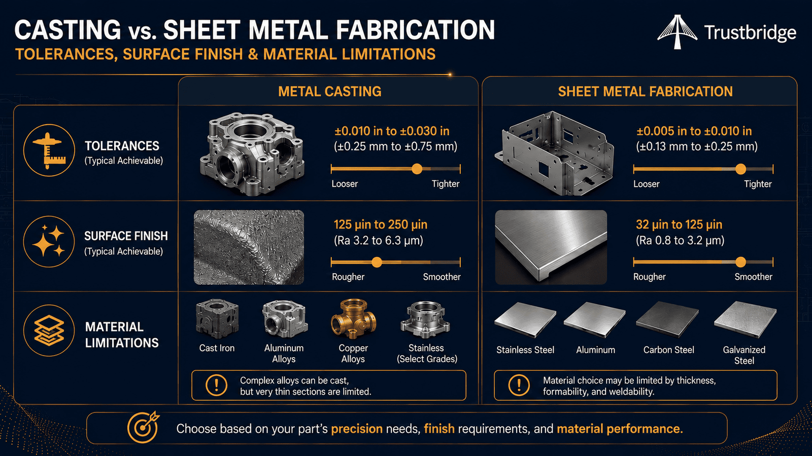
Geometry, volume, and structural needs usually narrow the choice to one process, but they don't tell the whole story, and skipping this part of the review is a common way a design ends up needing an unplanned round of secondary machining or a late material swap. Tolerances determine whether a part will actually fit and locate the way the CAD model says it will, and the two processes default to very different tolerance bands before any machining gets added to tighten them up. Surface finish determines how a part looks and feels straight out of the mold or off the brake, which matters for cosmetic parts and functional ones alike — sealing surfaces and bearing fits are not forgiving of an unplanned finish. Material availability determines whether the alloy a design actually needs is even offered by the process under consideration, since casting and sheet metal draw from different, only partly overlapping material catalogs. Catching a mismatch here at the drawing stage is cheap; catching it at first-article inspection, after tooling or material has already been committed, is not. The three sections below lay out realistic default expectations for each, process by process.
Tolerances
Sand casting is the loosest of the common casting methods, typically holding around ±0.03 to ±0.125 inch (roughly ±0.75 to ±3 mm) depending on part size, corresponding to ISO 8062 grades in the CT9–CT13 range. Investment casting tightens that considerably, generally landing around ±0.005 to ±0.015 inch (±0.13 to ±0.38 mm) for small-to-mid-sized features, in the CT5–CT7 range. Die casting is tighter still — often ±0.002 to ±0.005 inch on critical features straight from the die, sometimes approaching machined-part accuracy without any secondary work at all. Sheet metal fabrication draws its tolerances from a different logic: laser-cut, flat-plane features typically hold ±0.005 to ±0.010 inch, but formed dimensions — anything measured across a bend — pick up additional variation from springback and typically run ±0.010 to ±0.030 inch, with roughly ±1° on bend angles. A dimension that crosses several bends stacks that variation further, which is why sheet metal drawings are usually toleranced feature-by-feature rather than with one blanket callout. As a rule of thumb, a well-run die-casting or investment-casting program can rival a laser-cut flat feature on tolerance, but nothing in either process family gets close to CNC machining's ±0.001 to ±0.005 inch without an added machining step.
Surface finish
As-cast surfaces vary enormously by method. Sand casting is the roughest of the common processes, typically Ra 250–1,000 microinches (roughly 6–25+ µm), with the exact number depending heavily on sand grain size and mold type green sand is coarser, resin- or shell-bonded sand considerably smoother. Investment casting improves on that substantially, usually landing around Ra 63–250 microinches (1.6–6.3 µm), smooth enough in many cases to skip machining on non-critical surfaces entirely. Die casting is smoother still, at roughly Ra 32–125 microinches (0.8–3.2 µm), and can push finer with vacuum-assisted or squeeze-casting variants. Sheet metal starts from a different baseline: the flat faces of a part inherit the mill finish of the raw sheet stock, and a common cold-rolled or 2B stainless mill finish is already quite smooth — often well under Ra 32 microinches — before any fabrication happens at all. What sheet metal doesn't give you for free is a clean edge: laser- and plasma-cut edges pick up discoloration, a heat-affected zone, and sometimes mill scale, and they almost always need deburring before they're weld- or paint-ready. In short, casting's finish is a direct function of the mold; sheet metal's finish is a direct function of the mill stock, plus whatever the cutting and forming steps leave behind on the edges.
Material limitations
Casting draws from its own material family more than people expect. Aluminum is the most versatile casting metal, castable by nearly every method from sand to die casting, but the alloys used for casting A380, A356, and similar are chosen for fluidity and mold-filling behavior, not the same wrought alloys, like 6061 or 7075, used in machined or sheet parts, so mechanical properties don't translate directly across the two catalogs. Zinc and magnesium alloys are common in die casting for small, detailed parts; cast iron and steel are more common in sand casting for larger, heavier components; and copper-based alloys and nickel superalloys are generally reserved for investment casting, where higher melting points and slower fill rates are easier to manage. Sheet metal fabrication, by contrast, is bounded mainly by gauge: most fabricators work comfortably between roughly 0.02 and 0.25 inch (0.5–6 mm), covering mild steel, stainless steel, aluminum, and galvanized steel as the default catalog, with copper and brass available for decorative or electrical work. Push much past a quarter inch and the material stops behaving like "sheet" at all — it becomes plate, needing waterjet or plasma cutting and heavier press-brake tooling rather than standard laser-and-brake processing. Neither limitation is usually the deciding factor on its own, but a material call-out that assumes casting-grade properties from a sheet alloy, or the reverse, is a common way a design quietly becomes unmanufacturable as specified.
Tooling Cost and Lead Time Differ Sharply and Often Decide It for Early-Stage Teams
Once geometry, structural needs, tolerance, finish, and material have narrowed the field to a technically valid process — and sometimes both processes are still technically valid — the practical question for most early-stage teams stops being technical and becomes financial and logistical instead. What does it cost to get started, and how long until a real, testable part exists? These questions matter more than they might seem for a team that hasn't validated its design yet, because tooling is a sunk cost the moment it's cut: change the geometry after that point and some or all of that investment is gone, on top of whatever time is lost re-cutting it. Lead time compounds the same risk from a different angle — a long lead time locks a team into today's design for months, during which real-world feedback, part failures, or a pivot in the product itself can make that committed geometry obsolete before it ever ships. For a validated, stable design headed into real production, neither risk looms nearly as large, which is exactly why the right process can — and often should — change as a program matures. The two sections below break down what each process actually costs to tool and how long each realistically takes to turn into a part.
Tooling cost
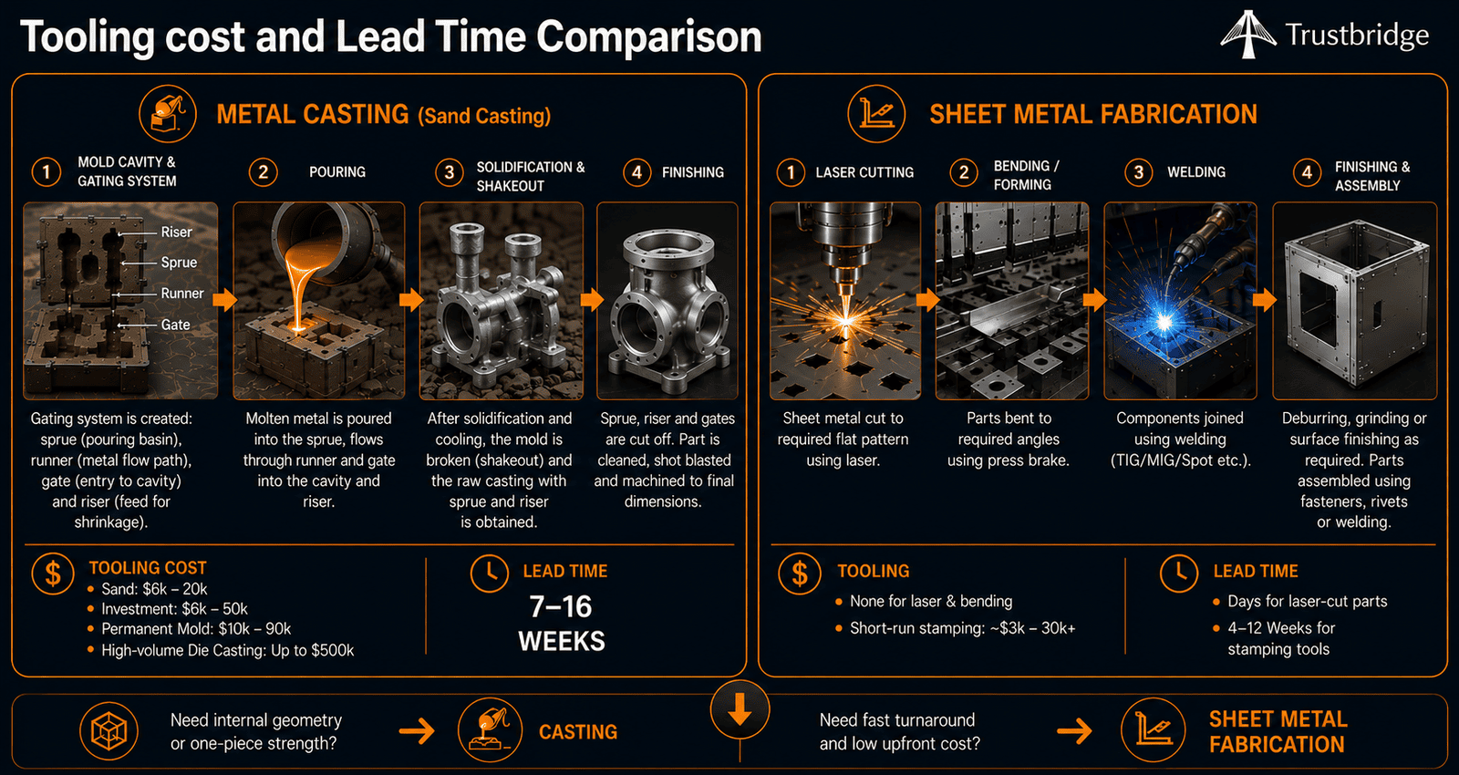
A metal casting service nearly always means paying for tooling before the first good part comes off the line. Sand casting tooling typically runs $6,000–$20,000; permanent mold tooling runs roughly $10,000–$90,000; investment casting tooling generally lands around $6,000–$50,000; and across casting methods as a whole, tooling can run as high as $500,000 for complex, high-volume die casting programs. Sheet metal fabrication services need no hard tooling at all for laser cutting or press-brake work a CAD file translates almost directly into a cutting or bending program, which is a large part of why quotes and first parts can turn around so quickly. Tooling only enters the picture with metal stamping, and even there the investment is comparatively modest: roughly $3,000–$30,000-plus for short-run stamping tools, a fraction of casting's upper range. For an early-stage team without a fully validated volume yet, that gap in upfront risk is often the deciding factor all by itself, well before geometry or structural needs get weighed at all nobody wants to be the team explaining a five-figure tooling write-off after a design pivot.
Lead time
Realistic lead times for a custom casting project run roughly 7 to 16 weeks all-in, with tooling design and fabrication usually the longest single stage in that window. That's workable once a part is validated and heading into real production; it's a much harder sell for a design that's still likely to change, since every revision after tooling is cut adds cost and time straight back onto the schedule, sometimes requiring a second tool entirely. On-demand sheet metal fabrication services, with no tooling to build, can turn parts around in a matter of days rather than weeks; even short-run stamping tooling, at roughly 4 to 12 weeks, still beats a full casting program's timeline. And for the earliest validation loops, 3D printing services can produce a form-check part in a day or two without touching either process's tooling at all, letting a design settle before a metal casting service or a sheet metal fabrication service gets involved for real.
Conclusion
Geometry tells you what's structurally possible, volume tells you what's economically sensible, and structural needs tell you what will actually survive its service life over time — but tooling cost and lead time are what usually decide it in practice, especially before a design has fully settled. Lay all four factors side by side and most parts have a reasonably clear answer. Just as often, though, the honest answer for an early-stage design is neither casting nor sheet metal yet — it's a machined or printed part that buys enough time to get the geometry right before committing to either process's tooling. Revisit the decision once volume firms up and the design stabilizes; the right process at 20 units validated in a prototype run is often genuinely different from the right process at 5,000 units in full production, and there's nothing wrong with changing processes as a program matures rather than forcing one choice to cover its entire lifecycle. The goal isn't picking the "better" process in the abstract — it's picking the one that fits where the part actually is right now.
If you're weighing a metal casting service against a sheet metal fabrication service for a real, physical part, send over the drawing along with your target volume and timeline. We'll tell you which process — and which of our shop partners actually fits your geometry, volume, and timeline, rather than steering you toward whichever one happens to be easiest for us to quote.
Frequently Asked Questions
1. How do I choose between metal casting services and sheet metal fabrication services?
The right choice depends on your part's geometry, production volume, structural requirements, material, tolerances, tooling budget, and lead time. Metal casting services are generally better for complex three-dimensional parts with internal cavities and high production volumes, while sheet metal fabrication services are often the better option for brackets, enclosures, chassis, and other parts made from flat stock, especially in low- to medium-volume production.
2. When is metal casting a better choice than sheet metal fabrication?
Metal casting is typically the better option when a part requires complex geometry, integrated ribs or bosses, varying wall thicknesses, or internal passages that cannot be produced efficiently from sheet metal. Although casting involves higher tooling costs and longer lead times, it often becomes the most cost-effective manufacturing process for large production runs.
3. How do tooling costs and lead times compare between casting and sheet metal fabrication?
Tooling for metal casting can require a significant upfront investment and lead times of several weeks before production begins. In contrast, most sheet metal fabrication services require little or no dedicated tooling for laser cutting and press-brake forming, allowing prototypes and production parts to be delivered much faster. For early-stage products or designs that may still change, sheet metal fabrication usually offers greater flexibility and lower financial risk.
4. Can tight tolerances and surface finish requirements affect the manufacturing process I should choose?
Yes. Tolerance, surface finish, and material requirements can significantly influence process selection. Some casting methods can achieve relatively tight tolerances, but highly precise features often require secondary machining. Sheet metal fabrication provides excellent accuracy for flat features but may introduce variation across formed bends. Evaluating these requirements early helps reduce machining costs, improve manufacturability, and avoid costly design changes later in production.