
Grooving Tool Deflection: Why Your Groove Width Is Never What You Programmed
Preamble
Grooving operations often produce dimensional variation even when programmed toolpaths appear correct. Many suppliers struggle with undersized grooves, inconsistent wall geometry, or unstable surface finish because grooving tool deflection changes cutter behavior during the cut. Insert geometry, feed direction, pressure angle, and tool overhang all influence how the cnc tool reacts under cutting load. Without understanding these hidden force interactions, machining teams risk inconsistent groove dimensions and unnecessary production adjustments. By improving cnc machine and programming strategies while optimizing grooving tool stability, suppliers can significantly improve groove accuracy, repeatability, and overall machining reliability.
Introduction
Grooving operations appear simple on the surface.
The tool enters the material, cuts to width, and exits the groove.
Yet many machining teams discover that the finished groove width rarely matches the programmed value exactly, even when offsets and machine calibration appear correct.
This happens because grooving tools behave differently under cutting pressure than many operators expect.
As cutting forces increase, the cnc tool deflects slightly during engagement. That movement changes actual cutting position, affects groove geometry, and creates dimensional variation that may not appear inside simulation or dry-run verification.
These problems become even more noticeable during deep grooves, narrow-width features, interrupted cuts, or difficult-material machining conditions.
For every tight-tolerance machining supplier, understanding how grooving forces influence real cutter behavior is essential for maintaining groove accuracy and machining consistency.
Restated Insight: Groove width errors are often caused by cutting-force deflection rather than incorrect programmed dimensions.
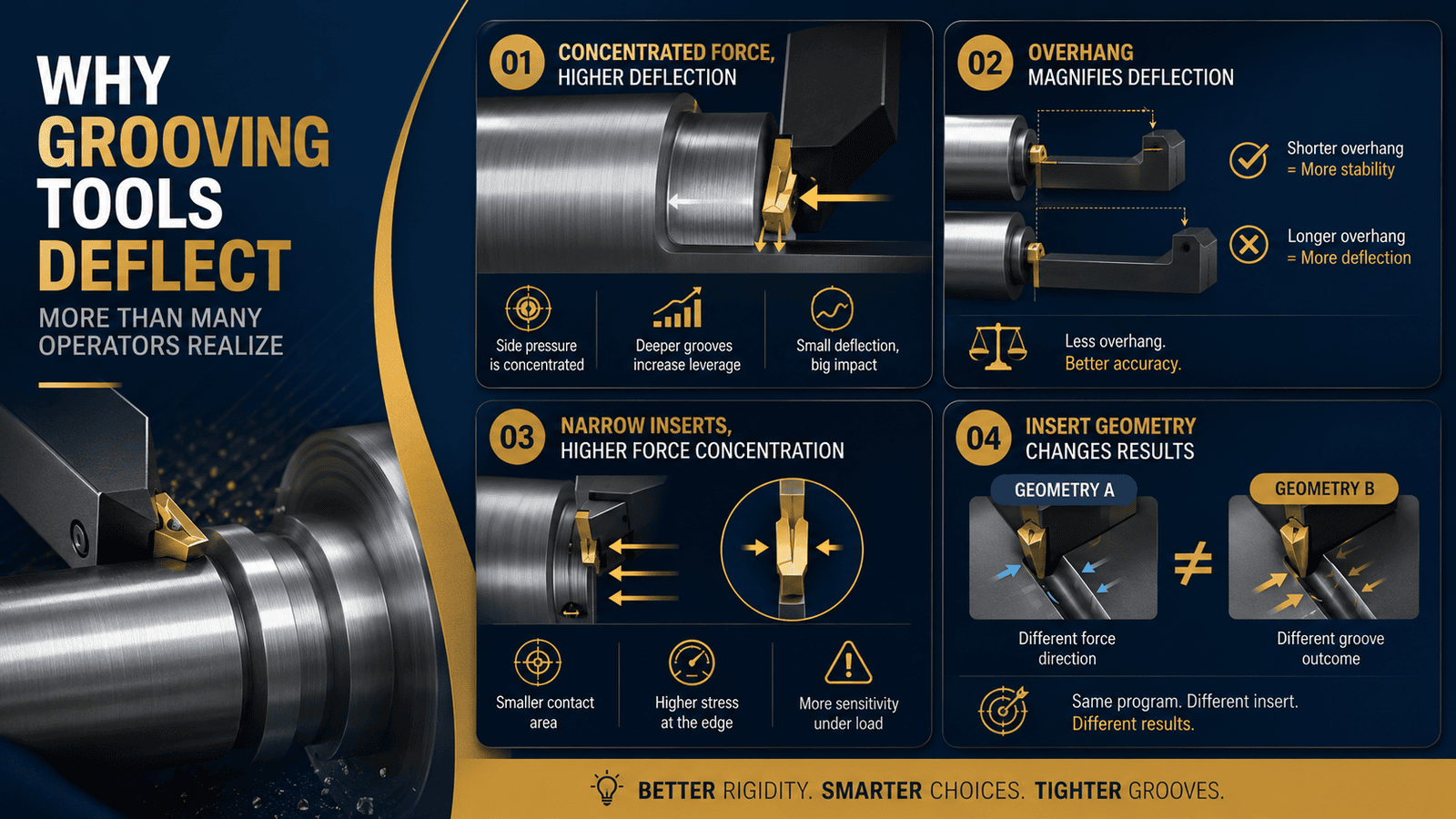
Why Grooving Tools Deflect More Than Many Operators Realize
Grooving tools operate under concentrated side pressure during cutting.
Unlike broader turning tools that distribute cutting forces more evenly, grooving inserts experience highly localized force loading inside narrow engagement zones.
As groove depth increases, the leverage acting against the toolholder also increases.
This creates small but highly influential deflection movement during machining.
- Tool Overhang Magnifies Deflection
Longer tool extension increases leverage against the holder during cutting.
Even slight additional overhang can significantly increase side movement under load.
This changes groove width consistency and often creates taper variation across deeper grooves.
Reducing unnecessary overhang improves tool rigidity and stabilizes groove dimensions.
- Narrow Inserts Create Higher Force Concentration
Very thin grooving inserts concentrate cutting pressure into smaller contact areas.
This increases stress at the cutting edge and magnifies deflection sensitivity during heavy engagement.
Programming of cnc machines should account for these force characteristics when selecting feed rates and engagement depth.
Insert Geometry Changes Groove Accuracy More Than Many Shops Expect
Insert geometry directly affects cutting force direction and chip evacuation behavior.
Different insert designs distribute cutting pressure differently across the groove walls and cutter edge.
This means two inserts cutting the same groove may produce different dimensional results under identical programming conditions.
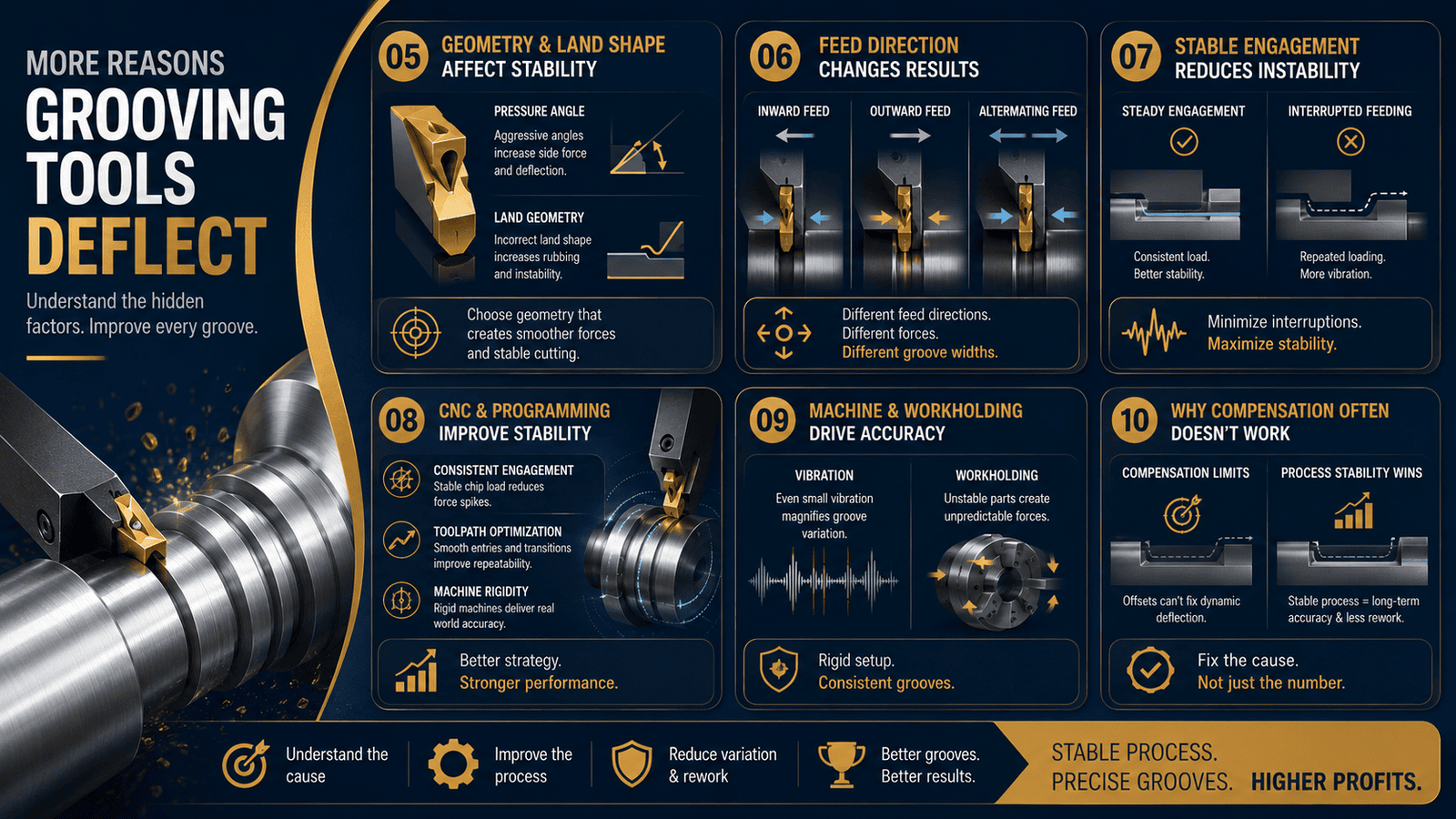
- Pressure Angles Influence Side Deflection
Aggressive pressure angles increase lateral cutting force during groove engagement.
This pushes the cnc tool sideways during cutting and changes final groove width.
Certain insert geometries create smoother force distribution and improve dimensional stability significantly.
Selecting insert geometry based on actual cutting behavior often matters more than simply choosing harder grades.
- Insert Land Geometry Affects Cutting Stability
The insert land controls how cutting forces transfer into the material during engagement.
Incorrect land geometry can increase rubbing, heat concentration, and unstable chip formation.
This creates inconsistent cutting load and accelerates groove variation during longer production runs.
For every machined components supplier, stable insert geometry selection plays a major role in maintaining dimensional repeatability.
Feed Direction Quietly Changes Groove Width Results
Many programmers focus heavily on feed rate while overlooking how feed direction itself affects tool stability.
Cutting force direction changes depending on whether the tool feeds inward, outward, or alternates direction during groove expansion.
These force differences directly influence cutter deflection behavior.
- Radial Feed Direction Changes Tool Pressure
Inward radial feeding often increases compressive force against the toolholder during deeper cuts.
Outward feeding may reduce certain side loads but create different vibration characteristics depending on material behavior.
Testing feed direction strategies under real production conditions helps improve groove stability.
- Interrupted Feeding Creates Instability
Frequent retracts and re-engagement cycles create repeated loading variation at the cutter edge.
This increases vibration potential and creates inconsistent groove dimensions over time.
Stable engagement strategies generally produce more predictable groove geometry and improved surface quality.
CNC Machine and Programming Strategies Improve Groove Stability
Stable grooving performance depends heavily on programming consistency and machine rigidity.
Even high-quality inserts struggle when cutting forces fluctuate excessively throughout the operation.
Modern cnc machine and programming workflows help reduce this instability through better motion control and engagement management.
- Consistent Engagement Reduces Deflection Variation
Maintaining stable chip load reduces sudden force spikes acting against the cutter.
This stabilizes tool pressure and improves groove dimensional consistency throughout the operation.
Adaptive feed adjustments can help maintain more stable engagement during difficult materials or deeper grooves.
- Toolpath Optimization Improves Repeatability
Smooth entry motion, stable feed transitions, and controlled retract sequencing improve overall groove stability significantly.
Well-optimized toolpaths reduce vibration and distribute cutting load more evenly across the insert edge.
This improves both surface finish and long-term cutter life.
Machine Rigidity Still Determines Real-World Groove Accuracy
Many groove problems blamed on tooling are actually machine stability problems.
Weak fixturing, turret movement, spindle vibration, or poor workholding all influence how the cutter behaves during engagement.
Small machine instability becomes highly visible during narrow grooving operations.
- Vibration Magnifies Groove Variation
Even low-level vibration changes cutting pressure distribution continuously during groove formation.
This creates inconsistent side loading against the insert and reduces dimensional accuracy.
Rigid machine setups improve both groove stability and insert life.
- Workholding Stability Protects Groove Consistency
Part movement during grooving creates highly unpredictable force variation.
Stable workholding reduces chatter and improves repeatable groove geometry throughout production runs.
For every advanced machining supplier, workholding stability remains critical for maintaining precision groove performance.
- Why Groove Compensation Often Fails to Solve the Real Problem
Many shops attempt to correct groove variation by adjusting offsets repeatedly.
While compensation may temporarily improve dimensions, it often fails to address the underlying instability creating the variation.
This leads to constant offset adjustments throughout production.
- Compensation Cannot Eliminate Dynamic Deflection
Tool deflection changes continuously based on engagement, material behavior, and heat generation.
Static offset compensation cannot fully correct constantly changing cutting forces.
True stability comes from reducing the deflection source itself.
- Process Stability Improves Long-Term Accuracy
Stable tooling, rigid setups, optimized geometry, and consistent programming reduce the need for constant operator intervention.
The most profitable machining environments are usually the most repeatable, not simply the most aggressive.
Conclusion
Groove width errors are rarely caused by programmed dimensions alone.
Tool deflection, insert geometry, feed direction, cutting pressure, and machine rigidity all influence how the cnc tool behaves during real cutting conditions.
By improving cnc machine and programming workflows, stabilizing cutting engagement, and selecting insert geometry based on force behavior rather than catalog recommendations alone, suppliers can significantly improve groove accuracy and machining repeatability.
For every tight-tolerance machining supplier, understanding how cutting forces influence groove formation is essential for achieving stable and predictable production performance.
If your shop is struggling with inconsistent groove widths, unstable insert life, or repeated offset adjustments, the issue may be deeper than simple tooling wear.
Reviewing cutter geometry, feed direction, machine rigidity, and cnc machine and programming workflows together often reveals hidden instability affecting groove accuracy.
Companies like Vulcury help suppliers improve precision machining performance through production-focused workflow optimization, tooling stability analysis, and advanced machining strategies designed for real-world manufacturing environments.
By improving process stability at the system level, suppliers can reduce variation, improve groove repeatability, and strengthen overall machining consistency.
Frequently Asked Questions
1. Why does groove width differ from the programmed dimension in CNC machining?
Groove width variation is often caused by grooving tool deflection during cutting rather than incorrect programmed values. As cutting forces increase, the cnc tool bends slightly under load, changing the actual cutting position and creating dimensional differences between the programmed groove width and the finished part.
2. How does tool overhang affect grooving accuracy?
Longer tool overhang increases leverage against the toolholder during cutting, making the grooving tool more susceptible to side deflection and vibration. Even small increases in overhang can reduce groove consistency, create taper variation, and negatively affect surface finish during deep groove operations.
3. How do insert geometry and feed direction influence groove stability?
Insert geometry affects cutting-force direction, chip evacuation, and side pressure against the cutter. Feed direction also changes how cutting loads transfer into the toolholder. Certain combinations of insert geometry, pressure angle, and feed strategy create higher lateral force, increasing groove width variation and machining instability.
4. Why do repeated offset adjustments fail to permanently fix groove variation?
Offset compensation only adjusts the programmed position—it does not eliminate the underlying cutting-force instability causing the deflection. Changes in material behavior, heat generation, vibration, and tool pressure continuously alter cutter movement during machining. Improving cnc machine and programming stability, tool rigidity, and workholding consistency provides a more reliable long-term solution.