
One Part, Six Processes: How Material and Process Selection Changes Everything About Cost and Performance
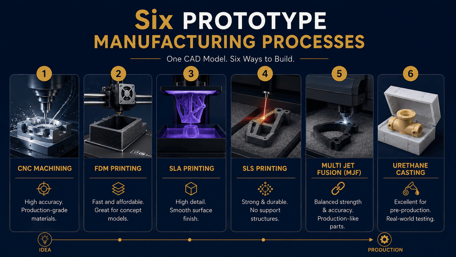
A single CAD model can produce dramatically different results depending on the manufacturing process and material selected. CNC machining, FDM, SLA, SLS, Multi Jet Fusion (MJF) and Urethane casting each offer unique advantages and limitations in cost, strength, accuracy, surface finish, scalability, and production readiness. Understanding these differences helps industrial designers and product development teams select the right process for every stage of development, reduce engineering risk, and create a smoother path from prototype to production.
Introduction
Completing a CAD model is only the beginning of product development. The same design can perform very differently depending on how it is manufactured. A bracket machined from aluminum behaves differently from one printed using FDM, while an SLA enclosure that looks production-ready may not survive functional testing because of its material properties.
Every manufacturing process affects strength, accuracy, surface finish, durability, lead time, and cost. Choosing the right process depends on what the prototype needs to validate—whether it's appearance, functionality, or production readiness. Making that decision early helps teams generate reliable engineering data and avoid costly redesigns later.
Why Process Selection Changes Everything
Many engineers assume that if two prototypes share the same geometry, they will perform the same way. In reality, the manufacturing process affects strength, dimensional accuracy, surface finish, repeatability, and long-term performance.
For example, CNC machining preserves the original properties of solid materials, while FDM builds parts layer by layer, creating directional strength differences. SLA produces excellent cosmetic quality but may not withstand repeated mechanical loading. SLS and Multi Jet Fusion create durable nylon components for functional testing, while urethane casting produces production-like parts for pilot runs and customer validation.
Process selection also influences wall thickness, achievable tolerances, post-processing, scalability, and overall manufacturing cost. Rather than asking which process is cheapest, engineers should choose the one that provides the most useful engineering data for the next stage of development.
Process One - CNC Machining
CNC machining is widely regarded as the benchmark for functional prototypes because it uses production-grade metals and engineering plastics that closely match the properties of final production parts. Material is removed from a solid block through precise cutting operations, allowing engineers to evaluate structural performance, dimensional accuracy, thermal behavior, wear resistance, and assembly fit under real operating conditions.
Engineers typically choose CNC machining when validating tight tolerances, threaded features, bearing fits, sealing surfaces, and load-bearing components. Because the prototype behaves much like the final manufactured part, it provides reliable engineering data that reduces uncertainty before production tooling is commissioned.
CNC machining supports a broad range of materials, including aluminum, stainless steel, titanium, brass, ABS, Delrin (POM), nylon, polycarbonate, and other engineering plastics. Depending on the machine and application, tolerances of approximately ±0.01 mm to ±0.05 mm are commonly achievable, with excellent surface finishes that can be further improved through polishing, bead blasting, anodizing, plating, or powder coating.
Although machining generally involves higher costs and longer production times than most additive manufacturing methods, it often becomes the most economical choice when prototype accuracy and functional validation are critical. Identifying design issues before production can prevent costly tooling modifications and engineering changes later in the product lifecycle.
Process Two - FDM 3D Printing
Fused Deposition Modeling (FDM) remains one of the most widely used rapid prototyping technologies because it offers fast turnaround and low manufacturing costs. Thermoplastic filament is deposited layer by layer to create physical models, allowing product teams to evaluate concepts quickly without significant investment.
FDM is particularly valuable during the early stages of development when designs change frequently. Engineers use it to assess ergonomics, packaging, assembly fit, enclosure layouts, and overall product geometry before committing to more expensive manufacturing methods. The ability to print updated designs within hours makes FDM an excellent tool for rapid design iteration.
Common FDM materials include ABS, PLA, PETG, nylon, TPU, carbon-fiber-filled polymers, and high-performance engineering filaments. Typical dimensional tolerances range between ±0.2 mm and ±0.5 mm depending on printer capability, while surface finish usually requires sanding, vapor smoothing, or painting for cosmetic applications.
Because parts are built layer by layer, mechanical strength varies depending on print orientation, making FDM less suitable for highly loaded structural components. Thin walls, fine features, and demanding tolerance requirements can also present challenges. However, for concept validation and early product development, FDM remains one of the fastest and most cost-effective prototyping methods available.
Process Three - SLA 3D Printing
Stereolithography (SLA) is often selected when appearance, fine detail, and dimensional precision are the highest priorities. Using ultraviolet light to cure liquid photopolymer resin, SLA produces exceptionally smooth surfaces, sharp edges, and intricate features that closely resemble finished consumer products.
Because of its visual quality, SLA is widely used for industrial design reviews, customer demonstrations, investor presentations, marketing samples, and ergonomic evaluations. Designers also use it to verify complex geometries, intricate textures, and small design features that are difficult to reproduce using other rapid prototyping methods.
SLA materials include standard, tough, flexible, transparent, high-temperature, and engineering resins designed for specialized applications. Dimensional accuracy is typically within ±0.1 mm, and surface finish often requires only minimal post-processing such as washing, UV curing, sanding, or painting.
Despite its excellent appearance, SLA is not always suitable for demanding functional testing. Most photopolymer resins are more brittle than production thermoplastics and may crack or deform under repeated stress. Engineers should therefore use SLA primarily for validating aesthetics, fit, and design intent rather than long-term mechanical performance.
Process Four - SLS 3D Printing
Selective Laser Sintering (SLS) bridges the gap between rapid prototyping and functional product validation by producing durable engineering components without the need for support structures. A laser selectively fuses powdered material layer by layer while the surrounding powder supports the geometry throughout the build process, allowing highly complex parts to be manufactured with exceptional design freedom.
SLS is commonly used to produce snap-fit assemblies, internal channels, lightweight lattice structures, living hinges, and complex geometries that are difficult to machine conventionally. Because there are no support structures to remove, designers have greater flexibility to optimize products for function rather than manufacturability.
Most SLS parts are manufactured using engineering-grade nylon materials that provide excellent strength, wear resistance, and relatively uniform mechanical properties. Typical tolerances range between ±0.2 mm and ±0.3 mm, with medium-quality surface finishes that can be improved through bead blasting, dyeing, vapor smoothing, or coating.
Compared with FDM, SLS produces stronger and more reliable functional prototypes while still supporting rapid design changes. It has become a preferred choice for engineering teams that require production-like performance before investing in tooling or transitioning to larger manufacturing volumes.
Process Five – Multi Jet Fusion (MJF)
Multi Jet Fusion (MJF) has become one of the most capable additive manufacturing technologies for engineers who need prototypes that closely resemble production parts. Like SLS, it uses nylon powder, but instead of relying only on a laser, MJF applies fusing and detailing agents before heat is introduced. This produces parts with more consistent mechanical properties, finer feature resolution, and improved dimensional consistency across larger batches.
Unlike desktop 3D printing technologies, MJF is suitable for both functional prototyping and low-volume production. Engineers often choose it for snap-fit testing, enclosures, brackets, jigs, fixtures, and end-use components where repeatability is important. Because multiple identical parts can be produced in one build, MJF is frequently used during bridge manufacturing before injection molding tools are ready.
Common materials include PA12, PA11, glass-filled nylon, and flame-retardant nylon grades. These materials provide an excellent balance of strength, durability, chemical resistance, and fatigue performance. Standard dimensional tolerances generally range around ±0.3 mm or ±0.3% depending on part size, making the process suitable for many production-intent applications.
Surface finish is smoother and more uniform than traditional SLS, although parts still benefit from bead blasting, dyeing, polishing, vapor smoothing, or painting when cosmetic quality is important. Minimum wall thickness typically starts around 0.8–1 mm for most geometries, while average lead times range from three to seven business days depending on build volume.
For product teams evaluating rapid prototyping methods, MJF offers one of the closest experiences to production-quality additive manufacturing without the cost and lead time associated with tooling.
Process Six – Urethane Casting
Urethane casting fills the gap between prototyping and mass production. Instead of machining every part or printing each component individually, a master pattern is first created using CNC machining or 3D printing. That master is used to produce a silicone mold, which can then cast multiple polyurethane parts that closely resemble injection-molded components.
This makes urethane casting particularly attractive for pilot production, customer samples, engineering validation, and market testing. Companies can manufacture dozens of production-like parts without investing in expensive steel molds, allowing them to validate demand before committing to injection molding.
Available materials include rigid polyurethane resins, ABS-like materials, polypropylene-like grades, rubber-like elastomers, transparent resins, and high-temperature formulations. While these materials cannot perfectly replicate every production plastic, they often provide an excellent approximation for functional evaluation.
Typical tolerances are around ±0.2–0.3 mm depending on geometry and mold condition. One of the biggest strengths of urethane casting is its outstanding cosmetic quality. Silicone molds faithfully reproduce textures, colors, gloss levels, and fine details, creating prototypes that look remarkably similar to final production parts. Additional post-processing may include painting, texture matching, polishing, silk-screen printing, and custom color matching.
Wall thickness generally begins around 1–1.5 mm, although uniform sections improve mold life and casting consistency. Lead times usually range between seven and fifteen business days, with each silicone mold capable of producing approximately 15–25 parts before replacement becomes necessary.
For companies launching new products, urethane casting provides an economical way to gather customer feedback, conduct pilot programs, and validate designs before making significant tooling investments.
How Material Selection Changes the Outcome
Selecting the manufacturing process is only part of the decision. The material used for the prototype has just as much influence on strength, durability, thermal performance, chemical resistance, and long-term reliability. Even when two parts are manufactured using the same process, different materials can produce completely different engineering results.
Metal prototypes are commonly machined from aluminum, stainless steel, titanium, brass, copper, or tool steel. Aluminum is lightweight, easy to machine, and suitable for functional testing. Stainless steel offers corrosion resistance and higher strength, while titanium is selected for aerospace and medical applications where high strength-to-weight ratio is important.
Engineering plastics used in CNC machining include ABS, Delrin (POM), Nylon, Polycarbonate, PTFE, and PEEK. Each offers different combinations of wear resistance, stiffness, thermal stability, and machinability. Choosing the correct plastic allows engineers to more closely simulate production performance.
Additive manufacturing also offers a wide range of materials. FDM commonly uses PLA, ABS, PETG, Nylon, TPU, and carbon-fiber-filled filaments. SLA offers standard resins, tough resins, flexible resins, high-temperature resins, and clear materials. SLS and MJF primarily use PA12, PA11, glass-filled nylon, and specialty engineering powders.
Material selection affects machining difficulty, print success rates, wall thickness limitations, post-processing requirements, production lead time, and overall project cost. More importantly, it determines whether prototype testing accurately represents the behavior of the final production product. Selecting a material simply because it is available or inexpensive often produces misleading validation results that create expensive engineering changes later.
Comparing Prototype Cost Versus Prototype Value
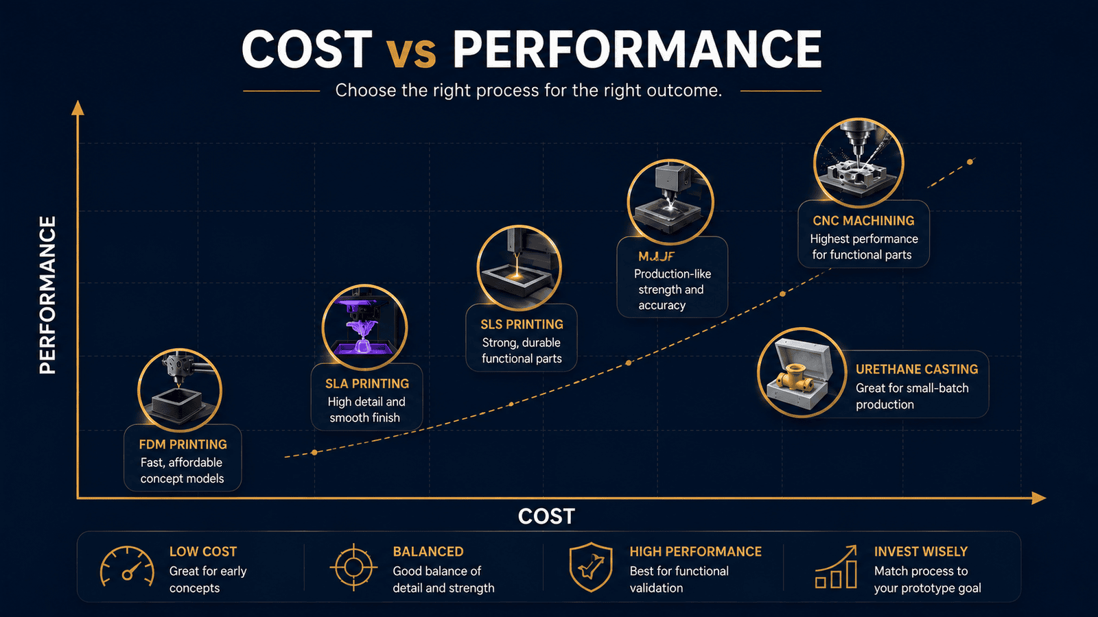
Prototype cost is important, but it should not drive every decision. A low-cost prototype that misses a critical design flaw can become far more expensive than one that prevents tooling changes or production delays.
Different development stages require different manufacturing methods. FDM supports rapid concept validation, SLA excels in visual models, CNC machining verifies functional performance, while SLS, MJF, and urethane casting help bridge the gap toward production.
The most valuable prototype is the one that provides the information needed to make the next engineering decision with confidence.
Connecting Process Selection to Production Success
Prototype manufacturing should support the final production strategy. When prototype materials and processes closely match production conditions, engineering data becomes more reliable, reducing redesigns and improving the transition to manufacturing.
Successful teams validate manufacturability, tolerances, material performance, and assembly requirements early in development. Every prototype should answer a specific engineering question and move the product one step closer to production.
Conclusion
The same CAD model can produce very different results depending on the manufacturing process and material selected. CNC machining, FDM, SLA, SLS, Multi Jet Fusion, and urethane casting each serve different purposes across product development.
Choosing the right process for the right stage helps teams generate better engineering data, reduce development risk, and move to production with greater confidence.
Choosing the right prototype manufacturing process is about making informed engineering decisions. At Trustbridge, we help product teams select the best combination of process, material, and manufacturing method for every stage of development.
By aligning prototypes with project goals, teams can reduce redesigns, improve product validation, and accelerate the transition from concept to production.
Frequently Asked Questions
1. Which prototype manufacturing process is best for my product?
The best prototype manufacturing process depends on what you need to validate. FDM is ideal for early design concepts, SLA for visual appearance and fine details, CNC machining for functional testing with production-grade materials, SLS and Multi Jet Fusion (MJF) for durable engineering prototypes, and urethane casting for low-volume, production-like parts before investing in tooling.
2. Why does the same CAD model produce different results with different manufacturing processes?
A CAD model only defines the geometry—not how the part is made. Each manufacturing process uses different materials, production methods, and tolerances, which affect strength, surface finish, dimensional accuracy, durability, and overall performance. That's why the same design can behave very differently depending on the chosen prototype manufacturing process.
3. How do I choose between CNC machining and 3D printing for prototyping?
Choose CNC machining when you need production-grade materials, tight tolerances, and reliable functional testing. Choose 3D printing when speed, lower cost, and rapid design iteration are the priority. The right choice depends on whether you're validating appearance, fit, functionality, or production readiness.
4. Why is material selection just as important as the manufacturing process?
The material determines how a prototype performs under real-world conditions, including its strength, stiffness, thermal resistance, wear characteristics, and durability. Even when two parts are made using the same manufacturing process, different materials can produce very different test results. Selecting the right material ensures prototype validation accurately reflects the performance of the final production part.