
Insert Geometry Decoded: Why the Chip Breaker Matters More Than Grade for CNC Tool Performance
Insert grade often receives most of the attention during tooling selection, but chip breaker geometry frequently has a greater impact on cutting stability, chip control, and machining performance. Different materials behave differently under load, and matching insert geometry to material characteristics is critical for optimizing CNC tool efficiency. In both steel and nonferrous metals machining, incorrect chip breaker selection can increase vibration, poor chip evacuation, and premature tool wear even when insert grade is correct. Understanding how insert geometry influences cutting behavior helps suppliers improve machining consistency, surface finish quality, and overall production efficiency.
Introduction
Tooling catalogs often emphasize insert grade selection, coating technology, and wear resistance. However, in real machining environments, chip breaker geometry frequently plays a more important role in cutting performance than the insert grade itself.
Chip flow, cutting pressure, heat generation, and surface finish are all heavily influenced by insert geometry. Selecting the wrong chip breaker can create unstable cutting conditions even when the insert material is technically correct for the application.
For every advanced machining supplier, understanding how geometry affects material behavior is essential for improving CNC tool performance and reducing production inefficiency.
Insert grade often receives most of the attention during tooling selection, but chip breaker geometry frequently has a greater impact on cutting stability, chip control, and machining performance. Different materials behave differently under load, and matching insert geometry to material characteristics is critical for optimizing CNC tool efficiency. In both steel and nonferrous metals machining, incorrect chip breaker selection can increase vibration, poor chip evacuation, and premature tool wear even when insert grade is correct. Understanding how insert geometry influences cutting behavior helps suppliers improve machining consistency, surface finish quality, and overall production efficiency.
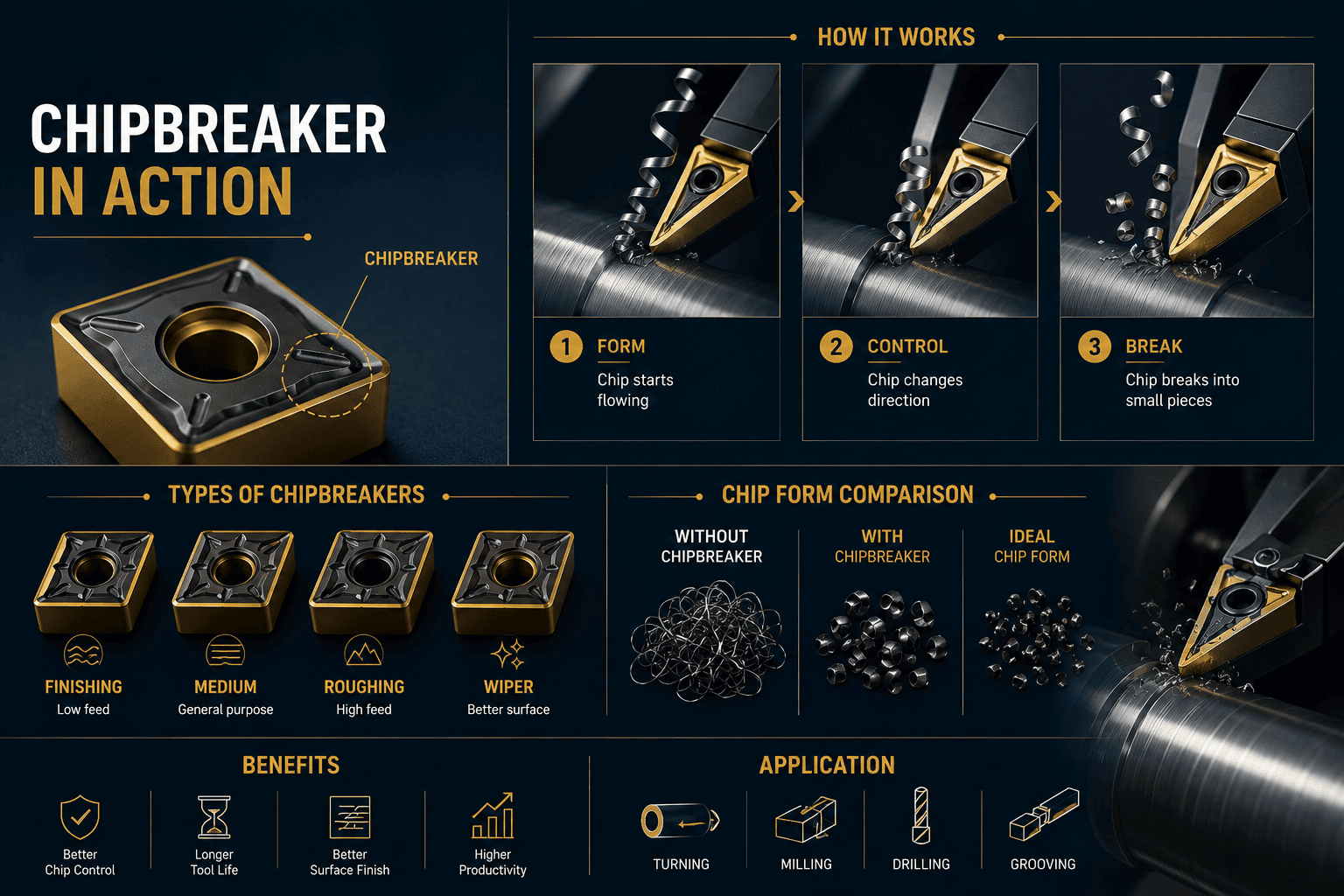
Selecting the Right Chip Breaker for Different CNC Machining Materials
Every material behaves differently under the cutting tool. Differences in hardness, ductility, thermal conductivity, and work-hardening characteristics all influence how chips form and how the insert should manage them. For this reason, selecting the correct chip breaker always starts with understanding the material being machined.
However, material selection alone is not enough. CNC Machine rigidity, spindle power, coolant delivery, and the machining operation itself also influence which geometry will provide the most stable results. Experienced machinists evaluate the complete machining system rather than selecting inserts solely from a catalog.
Steel, Stainless Steel, and Cast Iron Require Different Chip Breaker Designs
Although these materials are often grouped together, their machining behavior varies significantly.
Carbon and alloy steels generally produce long continuous chips that require controlled chip curling and fracture. Medium or roughing chip breaker geometries typically provide excellent chip control while maintaining stable cutting forces across a wide operating range.
Stainless steels present greater challenges because they are highly ductile and tend to work harden during machining. They often generate long, tough chips that resist breaking naturally. More aggressive chip breaker geometries help force tighter chip curling, improving chip evacuation while reducing the risk of bird-nesting around the tool.
Cast iron behaves very differently. Because it is naturally brittle, it produces small fragmented chips with minimal assistance. Chip breaker selection therefore focuses less on aggressive chip control and more on maintaining edge strength and resisting abrasive wear during long production runs.
Understanding these differences helps programmers improve chip evacuation while maintaining stable cutting conditions across a variety of ferrous materials.
Nonferrous Metals Need Free Chip Flow Instead of Aggressive Chip Breaking
Materials such as aluminum, brass, and copper require a completely different machining approach.
These metals are softer, more ductile, and highly susceptible to built-up edge. Instead of breaking naturally, they often produce long continuous chips that can wrap around the cutter if chip flow is restricted.
For these applications, insert geometries typically feature polished rake faces, positive cutting angles, and open chip channels that encourage chips to flow freely away from the cutting edge. Rather than aggressively breaking the chip, these geometries minimize friction and reduce material adhesion to the insert.
Using a steel-oriented chip breaker on aluminum frequently results in built-up edge, poor surface finish, increased spindle load, and inconsistent machining performance. Selecting an open geometry specifically designed for nonferrous materials improves dimensional accuracy while allowing higher cutting speeds and smoother chip evacuation.
Even when using inserts specifically designed for aluminum, programmers should still verify that feed rate, cutting speed, and machining strategy align with the geometry's intended operating window to achieve the best possible results.
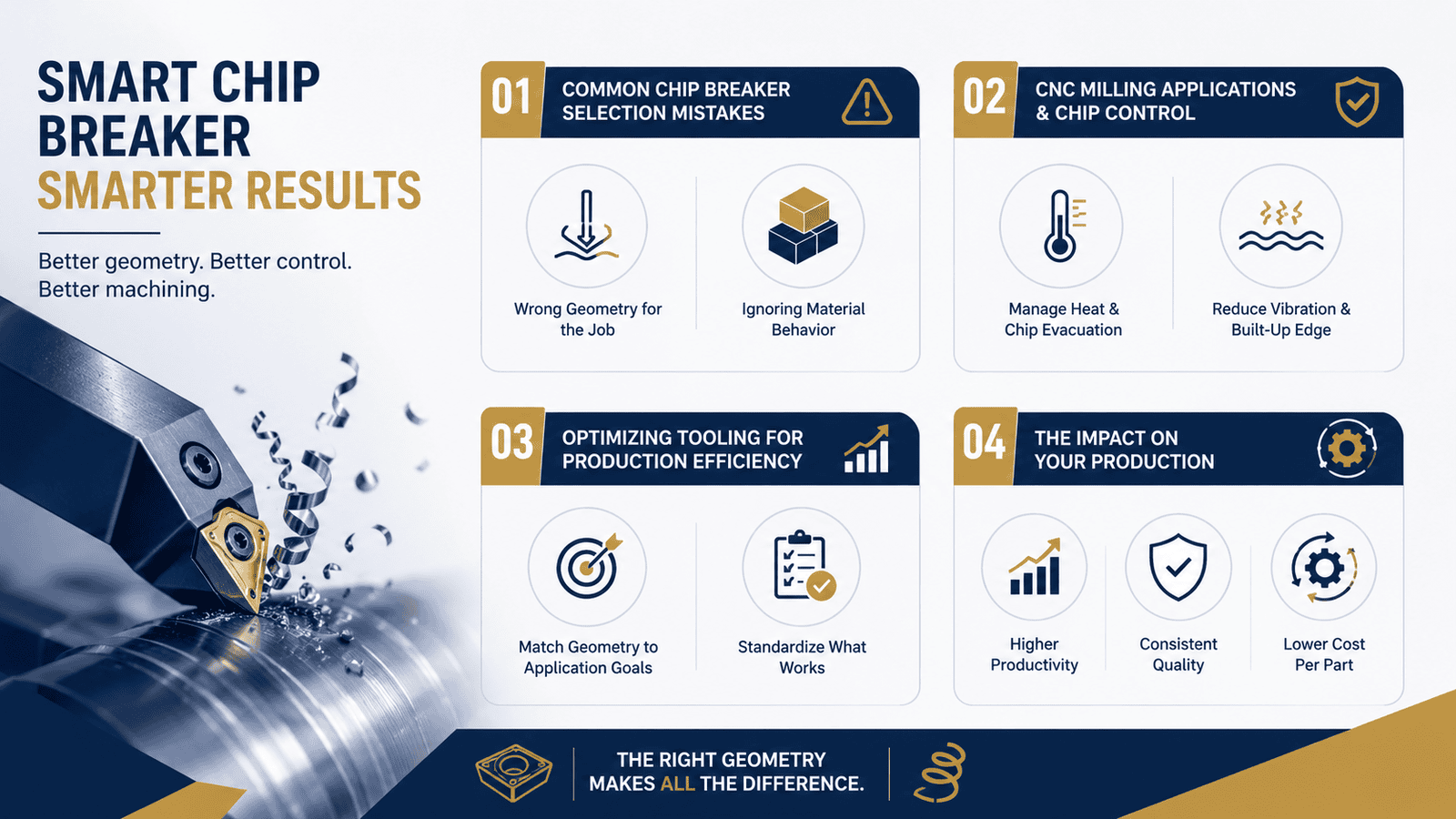
Common Chip Breaker Selection Mistakes
Many machining problems begin long before the spindle starts turning. They start when inserts are selected based only on catalog recommendations or previous jobs without considering the actual cutting conditions. While manufacturers provide general guidelines, real production environments often involve different materials, machine rigidity, depths of cut, and feed rates than those used during laboratory testing.
Understanding the limitations of each chip breaker helps suppliers avoid unnecessary tooling problems and build more predictable machining processes. Small changes in insert geometry can dramatically improve chip evacuation, surface finish, and tool life without changing the insert grade.
Using Finishing Geometry for Roughing Applications
Finishing inserts are designed to produce low cutting forces, fine surface finishes, and light chip loads. They perform exceptionally well during shallow finishing passes but are not intended for aggressive roughing operations.
When these geometries are used for heavier cuts, they often fail to break chips effectively. The result is long stringy chips, unstable cutting pressure, excessive insert wear, and increased vibration. Selecting a roughing geometry with a stronger chip breaker allows the insert to handle heavier chip loads while maintaining consistent chip control throughout the operation.
Ignoring Material-Specific Cutting Behavior
Different materials produce completely different chip characteristics, even when machining parameters remain similar. Mild steel, stainless steel, titanium, cast iron, and aluminum all require different chip breaker designs to achieve stable cutting.
Using the same insert geometry across multiple materials often creates inconsistent machining performance. Suppliers who match chip breaker geometry to material behavior rather than relying on one "universal" insert usually experience longer tool life, better chip control, and fewer production interruptions.
CNC Milling Applications and Chip Control
Chip breaker performance becomes even more important during cnc milling operations because the insert continuously enters and exits the material. This interrupted cutting action creates changing chip thickness, fluctuating cutting forces, and varying thermal loads throughout each cutter revolution.
Without the correct insert geometry, these constantly changing cutting conditions can reduce machining stability, increase vibration, and shorten insert life. Selecting the proper chip breaker helps maintain predictable cutting performance even during demanding milling applications.
Managing Heat and Chip Evacuation
Effective chip formation removes a significant amount of heat from the cutting zone. Well-controlled chips carry thermal energy away with them, reducing the amount of heat transferred into the insert and workpiece.
Poor chip control has the opposite effect. Chips remain near the cutting edge, increasing friction and accelerating wear. By selecting a chip breaker that consistently produces small, manageable chips, suppliers improve thermal stability while extending tooling life during long production runs.
Reducing Vibration and Built-Up Edge
Unstable chip formation often creates inconsistent cutting forces that lead to chatter and vibration. This not only affects surface finish but can also shorten spindle life and increase insert consumption.
Proper chip breaker geometry stabilizes cutting forces while minimizing built-up edge, particularly when machining softer materials. Stable cutting conditions improve dimensional accuracy, reduce secondary finishing work, and create a more predictable machining process across different production batches.
Optimizing Tooling for Production Efficiency
Improving machining performance is rarely about changing one variable in isolation. The most successful suppliers optimize insert geometry, machining parameters, tooling strategy, and machine capability together as part of a complete production system.
Rather than chasing the newest insert grade for every application, experienced machining teams focus on developing repeatable tooling standards that consistently deliver reliable results. This systematic approach reduces process variation while improving productivity over the long term.
Matching Geometry to Application Goals
Different machining operations place different demands on the cutting tool. Finishing passes require low cutting forces and excellent surface finish, while roughing operations prioritize chip control, material removal rates, and insert durability.
Selecting chip breaker geometry based on the actual production objective ensures the insert operates within its intended performance range. This improves machining consistency while reducing unnecessary tooling costs across multiple jobs.
Standardizing Successful Tooling Strategies
Many high-performing machine shops document successful insert combinations, cutting parameters, and chip breaker selections for recurring materials and applications. These proven setups become standardized processes that reduce operator variation and simplify programming decisions.
Standardization also makes training easier, improves production repeatability, and helps suppliers maintain consistent machining quality even as new operators or programmers join the team. Over time, these documented best practices become a valuable competitive advantage.
Conclusion
Insert geometry plays a critical role in machining performance, often influencing cutting stability and chip control more than insert grade alone.
By understanding how chip breakers interact with material behavior, cnc machine and programming conditions, and cnc milling strategies, suppliers can improve tooling efficiency, reduce vibration, and achieve more stable machining outcomes.
For every advanced machining supplier, optimizing chip breaker selection is essential for maintaining consistent cnc tool performance across different materials and production environments.
If your machining team is struggling with chatter, bore taper, or unstable long-bore machining performance, unsupported boring limitations may be affecting your production consistency.
Evaluating tooling rigidity, damping strategy, and machine behavior together can uncover hidden stability issues impacting bore accuracy.
Companies like Vulcury support suppliers with production-focused machining insights, helping teams optimize cnc tool performance, strengthen cnc machine and programming workflows, and improve long-bore machining reliability.
By combining realistic machining strategies with stable process control, suppliers can reduce vibration, improve bore quality, and achieve more predictable production outcomes.
Frequently Asked Questions
1. What is a CAM post-processor and why is it critical in CNC machining?
A CAM post-processor converts CAM-generated toolpaths into machine-specific CNC machine g code that a controller can execute. It serves as the link between CAM software and machine behavior. Even if a toolpath is correct, an improperly configured post-processor can generate unsafe motion, incorrect axis movements, or unstable machining conditions that affect overall cnc machine and programming performance.
2. How can post-processor errors be mistaken for machine failures?
Many post-processing errors create symptoms that resemble mechanical or controller problems. Incorrect arc output, unsafe rapid moves, coordinate transformation mistakes, or poor tool change sequencing can cause alarms, unexpected motion, poor surface finish, and positioning errors. As a result, programmers often blame the machine when the actual problem exists within the generated CNC machine g code.
3. What are the most common CAM post-processor mistakes in programming of CNC machines?
Common post-processing issues include arc interpolation errors, excessive line segmentation, unsafe clearance plane calculations, incorrect spindle and coolant sequencing, and tool length compensation mistakes. These hidden software output problems can lead to machine crashes, inconsistent machining performance, increased downtime, and reduced cnc tool accuracy even when the machine is mechanically sound.
4. How can advanced machining suppliers improve post-processor reliability and machining stability?
Advanced machining suppliers improve reliability by validating post-processors regularly, reviewing CNC machine g code output after software updates, performing machine simulation and dry-run verification, and standardizing proven post-processing workflows. Strong collaboration between programmers and machine operators also helps identify hidden motion issues early, reducing risk and improving long-term machining consistency.