
7 Plastics Injection Molding Design Rules That Improve Product Quality and Manufacturability
Introduction
Plastics injection molding is one of the most widely used manufacturing processes for producing complex plastic parts at scale. From consumer electronics housings to automotive components and medical devices, manufacturers rely on plastics injection molding to deliver consistent quality, tight tolerances, and cost efficiency. However, design decisions made early in development have a major impact on manufacturing success. For example, redesigning a molded component after tooling steel has already been cut can add two to four weeks to a project timeline and introduce significant tooling rework costs.
However, achieving reliable results requires more than simply creating a 3D model and sending it to production. Engineers and product designers must follow structured injection molding design guidelines that ensure parts can be manufactured efficiently without defects or unnecessary costs. Manufacturing outcomes in injection molding are influenced by factors such as flow length-to-thickness ratio, gate placement strategy, and cooling channel efficiency within the mold. These technical parameters directly affect how molten plastic fills, cools, and solidifies within the tooling.
Design decisions made early in development directly influence manufacturing lead times, tooling complexity, material consumption, and long-term product performance. When teams apply design for manufacturability principles, measurable improvements often follow. These include reduced defect rates, shorter molding cycle times, and extended tooling lifespan.
By combining strong engineering practices with thoughtful material selection in product design, teams can move efficiently from prototype to production while maintaining quality and scalability. The design rules discussed below provide practical guidance that engineers can apply when developing molded components. These principles are widely used across industries including automotive systems, consumer electronics, industrial equipment, and medical devices.
Why Design Rules Matter in Plastics Injection Molding
Designing plastic components without considering manufacturing constraints often leads to costly tooling modifications, longer development cycles, and inconsistent part quality. Injection molding requires careful planning because molten plastic flows through molds under pressure, cools through controlled thermal gradients, and solidifies under conditions influenced by material viscosity and mold temperature control.
When engineers apply proven injection molding design guidelines early in the product development cycle, they significantly reduce risks associated with manufacturing defects. These defects typically fall into three broad categories: flow-related defects such as short shots or weld lines, cooling-related defects such as warpage or sink marks, and structural issues such as stress fractures or weak load-bearing areas. Many manufacturers also use mold flow simulation tools during the design phase to predict how molten plastic will behave inside the mold cavity before tooling is manufactured.
Following structured design rules not only improves structural performance but also reduces production costs. Uniform material distribution can shorten cooling cycles, reduce resin usage, and improve molding consistency across high-volume production runs. These improvements translate directly into optimized manufacturing lead times and more predictable product quality.
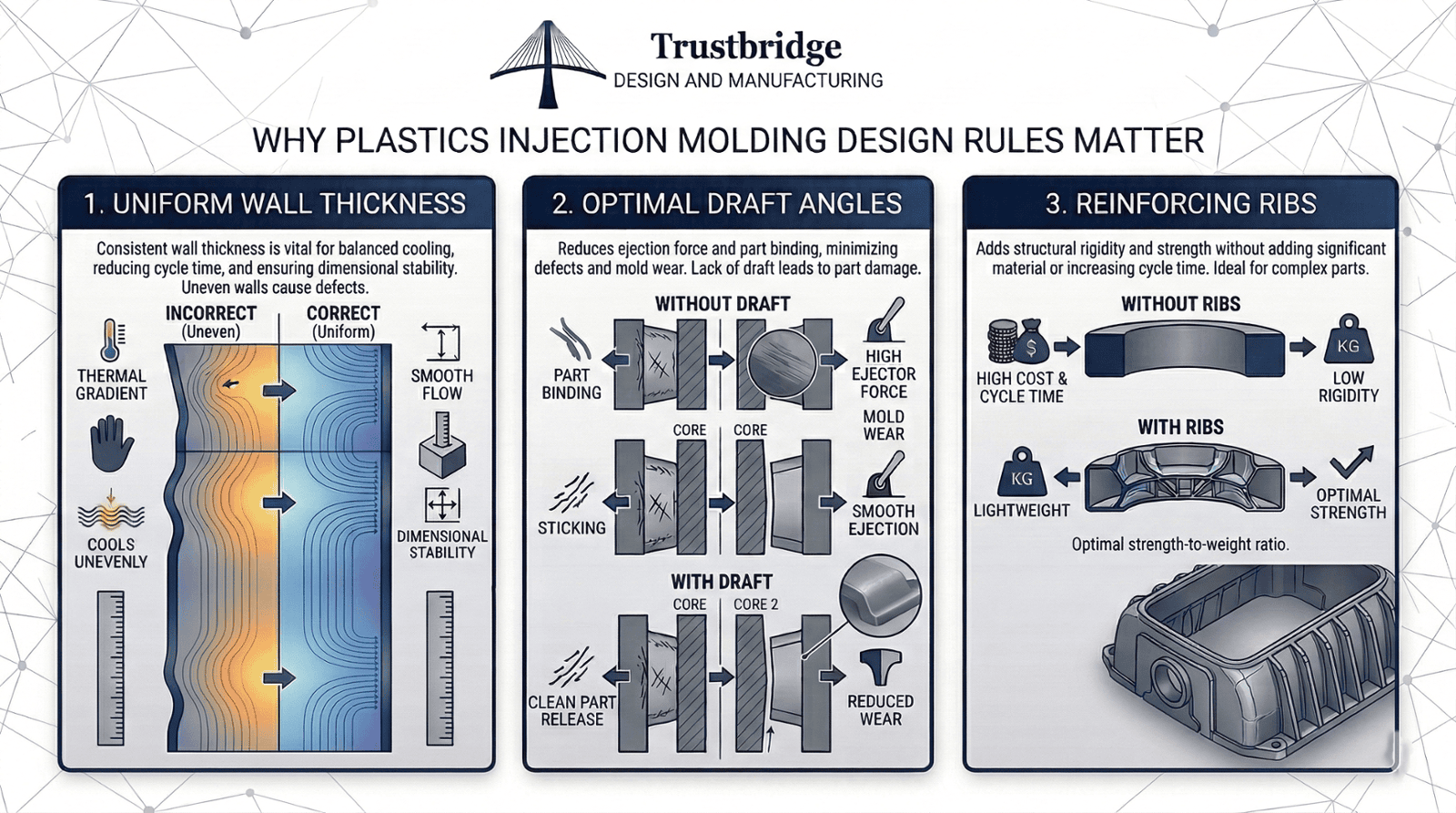
Rule 1 Maintain Consistent Wall Thickness
Maintaining uniform wall thickness is one of the most fundamental injection molding design guidelines. Consistency does not mean that every region of the part must have identical thickness, but rather that thickness should remain uniform within functional zones to promote stable cooling behavior. Most thermoplastic molded parts perform well within a general wall thickness range of approximately 1.0 mm to 4.0 mm depending on the selected material.
Variations in wall thickness can cause uneven cooling, which leads to warping, internal stresses, and dimensional inaccuracies. When molten plastic fills a mold cavity, thicker sections retain heat longer than thinner areas. This difference in cooling rates can create internal stress that distorts the final part or produces visible cosmetic defects.
Designers should also avoid abrupt transitions between thick and thin sections. Gradual transitions allow plastic to flow evenly through the cavity while reducing the likelihood of sink marks or structural weaknesses. Maintaining balanced wall thickness improves dimensional stability and ensures smoother mold filling during production.
Rule 2 Add Draft Angles for Easier Part Ejection
Once a molded part cools inside the mold, it must be ejected without damaging the component or the tooling. Draft angles are slight tapers applied to vertical surfaces that allow molded parts to release smoothly from the mold cavity.
Without draft angles, frictional resistance between the molded plastic and the steel surfaces of the core and cavity walls increases significantly. This friction can cause parts to stick during ejection, leading to scratches, deformation, or excessive force on ejector pins. Over time, repeated sticking can also accelerate mold wear and reduce tooling longevity.
Draft angles therefore play an important role in maintaining stable production cycles, particularly in automated manufacturing environments where consistent part release is essential for cycle efficiency.
- Recommended Draft Angle Guidelines
Industry design practices recommend draft angles in the range of approximately one to three degrees per vertical wall depending on material behavior and surface finish requirements. Deeper molded components generally require larger draft angles because the increased contact surface between the plastic and mold walls creates greater friction during ejection.
Surface finish also affects draft requirements. Textured surfaces or SPI finish grades increase friction and therefore require larger draft allowances to ensure reliable part release.
Incorporating proper draft angles during the early design stage supports design for manufacturability while improving mold durability and maintaining stable production cycle times.
Rule 3 Use Ribs to Improve Strength Without Increasing Thickness
Increasing wall thickness might appear to be a simple solution for strengthening a plastic component, but thicker sections often introduce non-uniform cooling behavior and volumetric shrinkage issues. Excess material also increases resin consumption, which directly raises production costs.
Instead, designers commonly use rib structures to reinforce molded components without significantly increasing part weight or material usage.
Ribs improve stiffness by increasing the moment of inertia and section modulus of a component. This structural reinforcement allows designers to maintain relatively thin walls while still achieving required strength and rigidity. Rib structures are frequently used in automotive dashboards, appliance housings, and electronics enclosures where lightweight design and structural integrity must coexist.
- Proper Rib Design Considerations
Effective rib design follows established dimensional guidelines. Rib thickness is generally recommended to remain within approximately 0.5 to 0.6 times the main wall thickness. This ratio helps prevent sink marks while still delivering meaningful reinforcement.
Rib height should typically remain within two to three times the wall thickness unless structural analysis confirms a larger dimension is acceptable. Ribs should also include a minimum draft angle of approximately 0.5 to 1 degree per side to allow proper mold release.
Spacing between ribs also plays an important role. Maintaining rib spacing of at least two to three times the wall thickness promotes balanced material flow and reduces the risk of warping. Properly engineered ribs support lightweight design strategies while maintaining manufacturability and structural reliability.
Rule 4 Design Smooth Transitions and Fillets
Sharp internal corners create several problems in plastics injection molding. They introduce high stress concentration factors (SCF), restrict molten plastic flow, and create areas where material stress can accumulate during operation.
These stress concentration points can weaken a component and increase the likelihood of cracking or fatigue over time.
Fillets, or rounded corners, allow molten plastic to flow more smoothly through the mold cavity while distributing mechanical stress more evenly throughout the part.
- Benefits of Fillets in Molded Parts
Adding fillets improves pressure distribution during the mold filling phase and reduces localized shear stress concentrations. This results in more uniform material flow and improved structural performance.
A common design guideline recommends that the outer radius of a fillet equal the inner radius plus the wall thickness. This geometry supports balanced material flow while also improving tooling durability by eliminating sharp steel edges inside the mold cavity.
Fillets also enhance product durability and aesthetics, particularly in components that experience repeated loading or mechanical stress. By improving both manufacturability and performance, fillets contribute to long-term product reliability.
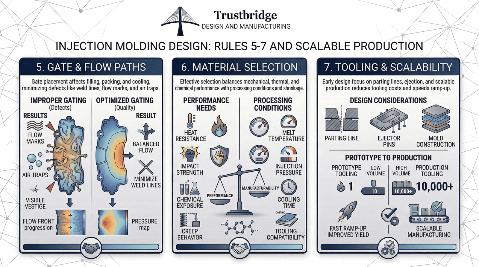
Rule 5 Plan Gate and Flow Paths Carefully
The gate is the location where molten plastic enters the mold cavity. Gate placement significantly affects how plastic fills the mold, how pressure is distributed during packing, and how the part cools during the molding cycle.
Improper gate placement can lead to flow marks, air traps, weld lines, or incomplete cavity filling. It may also create visible gate vestiges on cosmetic surfaces if the location is not carefully considered.
Engineers must therefore analyze part geometry to achieve balanced flow paths that maintain uniform pressure and temperature distribution during molding.
- Flow Optimization in Mold Design
Many manufacturers use mold flow simulation software to evaluate plastic flow behavior before tooling fabrication begins. These simulations analyze factors such as flow front progression, pressure drop across the cavity, cooling rates, and potential weld line formation.
By predicting molding behavior early, engineers can optimize gate placement and minimize the need for costly mold modifications later. Simulation also reduces the number of physical tooling trials required during validation.
As a result, optimized gating strategies improve part quality, reduce scrap rates, and shorten manufacturing lead times during mold qualification.
Rule 6 Select the Right Material for the Application
Material selection plays a central role in determining the performance and durability of injection molded components. Thermoplastics vary significantly in their mechanical properties, thermal behavior, and chemical resistance.
Effective material selection in product design must consider factors such as heat resistance, impact strength, creep behavior, chemical exposure, and dimensional stability. Another critical parameter is material shrinkage rate, which directly influences tooling dimensions and final part accuracy.
Different materials also require unique processing conditions such as specific melt temperatures, injection pressures, and cooling times. These parameters must align with mold design to ensure consistent production quality.
- Balancing Performance and Manufacturability
Some high-performance engineering plastics deliver exceptional strength and heat resistance but introduce additional processing challenges. These materials may require higher molding temperatures, longer cooling cycles, or specialized tooling coatings.
These processing requirements affect overall production cost by increasing energy consumption, tooling complexity, and molding cycle duration.
Selecting the appropriate material early in the design stage supports successful prototype validation testing and improves long-term product reliability once production begins.
Rule 7 Design With Tooling and Production in Mind
Injection molds are precision manufacturing tools that require significant upfront investment. Poorly designed parts often require tooling modifications that increase cost and delay production timelines.
Engineers must therefore consider mold parting lines, ejector pin placement, and mold construction during the design phase. Ignoring these factors may lead to cosmetic defects, structural weaknesses, or inefficient mold operation.
- Designing for Scalable Manufacturing
Parts optimized for tooling compatibility transition more smoothly from prototype development to full-scale manufacturing. Prototype tooling is often designed for lower production volumes, while production molds are engineered for durability and high cycle counts.
Designing with scalable manufacturing in mind allows companies to achieve faster production ramp-up, improved first-pass yield rates, and more predictable part consistency.
Applying design for manufacturability principles provides companies with a competitive advantage by enabling faster product launches and more efficient production scaling.
How Injection Molding Design Impacts Prototype to Production
Many product development teams underestimate how early engineering decisions influence manufacturing outcomes. In reality, early design decisions can lock in up to seventy to eighty percent of total manufacturing cost before production even begins.
Successful injection molding programs require close coordination between industrial designers, mechanical engineers, and manufacturing specialists.
Following established injection molding design guidelines improves collaboration between design and production teams while enabling more predictable supply chain planning. When these principles are applied consistently, manufacturers often see measurable improvements such as reduced scrap rates, improved first-pass yield during mold trials, and shorter T1 mold validation cycles.
These improvements translate into greater manufacturing stability, reduced production variability, and stronger competitive positioning in high-volume product markets.
Conclusion
Plastics injection molding is a sophisticated manufacturing process governed by complex interactions between thermal behavior, pressure dynamics, and precision tooling. Successful molded products depend on design decisions that account for these technical realities from the earliest stages of development.
Engineers who prioritize consistent wall thickness, optimized draft angles, rib reinforcement, smooth transitions, and strategic gate placement create parts that perform reliably while remaining efficient to manufacture.
When these principles are combined with careful material selection in product design and strong design for manufacturability practices, companies can dramatically improve production efficiency and product reliability.
Ultimately, successful injection molding programs begin long before tooling fabrication. They begin with engineering decisions that align product design with manufacturing realities.
Developing injection-molded products requires deep collaboration between engineering design and manufacturing strategy. Every decision—from part geometry to material selection—directly influences production efficiency, tooling reliability, and product quality.
Trustbridge supports product teams by connecting engineering development with global manufacturing expertise. By assisting with early design validation, supplier coordination, and production readiness, companies can minimize tooling revisions, stabilize manufacturing lead times, and reduce costly redesign cycles.
If your team is preparing the next generation of plastic products, working with experienced manufacturing partners can help transform complex design challenges into scalable production solutions.
Frequently Asked Questions (FAQs)
1. Why are injection molding design guidelines important for product quality?
Injection molding design guidelines help engineers create parts that can be manufactured efficiently without defects. By considering factors like wall thickness, draft angles, and gate placement early in the design process, teams can reduce issues such as warping, sink marks, and incomplete fills while improving overall product reliability.
2. How does design for manufacturability improve plastics injection molding outcomes?
Design for manufacturability ensures that plastic parts are optimized for the molding process before tooling begins. When engineers design with manufacturing constraints in mind, they can reduce tooling complexity, improve cycle efficiency, and shorten manufacturing lead times while maintaining consistent product quality.
3. Why is material selection important in plastics injection molding?
Material selection directly affects mechanical strength, durability, thermal resistance, and dimensional stability of molded parts. Choosing the right thermoplastic during product design helps ensure the component performs reliably in its intended application while remaining compatible with injection molding processing conditions.
4. How do proper design rules help transition from prototype to production?
When injection molding design rules are applied early, prototypes are developed with manufacturing scalability in mind. This reduces the need for redesigns after tooling is created and allows companies to move more smoothly from prototype to production while maintaining quality and predictable manufacturing lead times.