
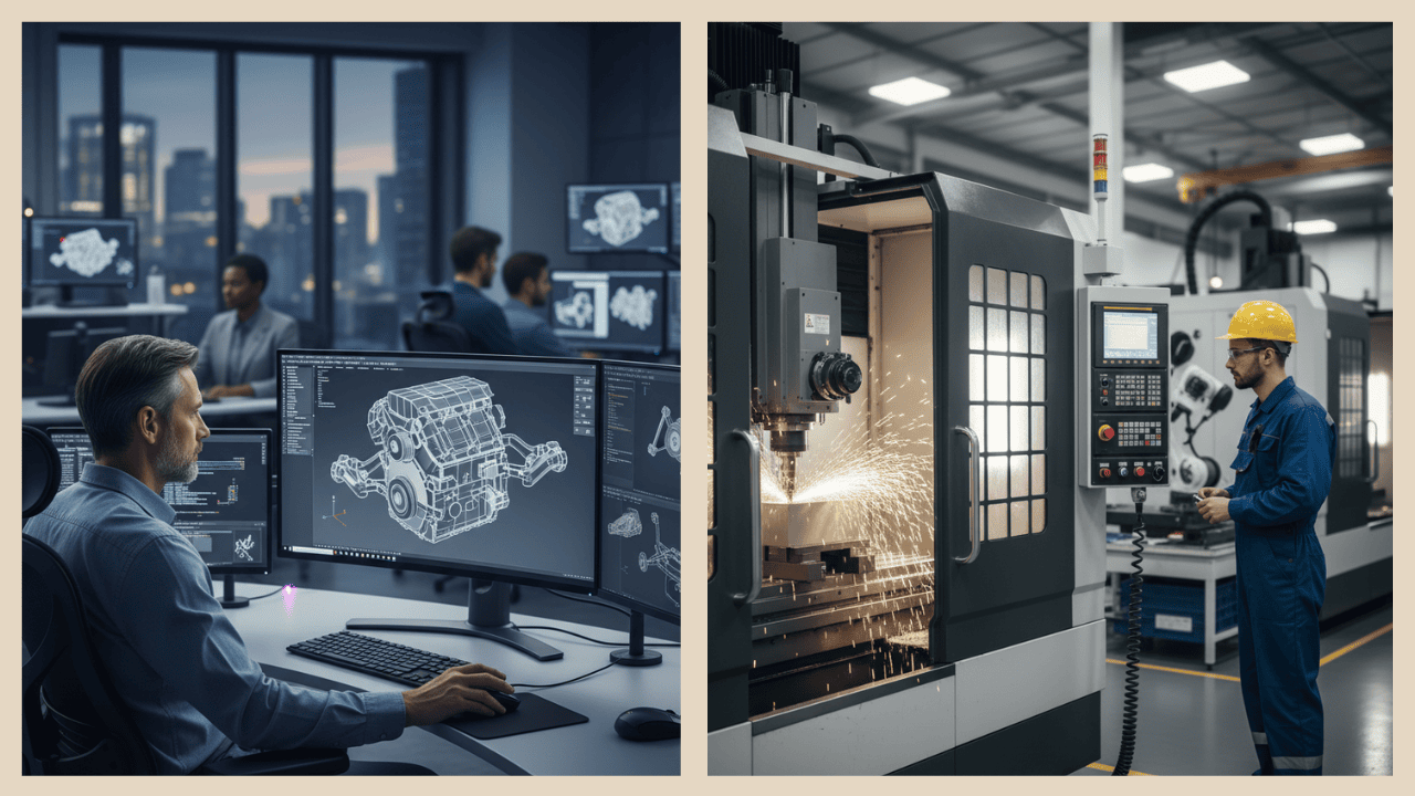
From CAD to CNC:
Design Decisions That Make-or-Break Manufacturability
You've just finished the perfect 3D model: sleek, complex, and functionally flawless in CAD. But when you hit the 'export' button, the real clock starts ticking up the clock that determines if your design will be an engineering marvel or a costly manufacturing nightmare. The digital blueprint often promises perfection that the physical shop floor can't deliver.
The transition from Computer-Aided Design (CAD) to Computer Numerical Control (CNC) is a critical, often unforgiving, filter. A simple, forgotten detail like an overly deep pocket, a sharp internal corner, or an unnecessarily thin wall can instantly spike material costs, multiply machining time, and even render your expensive workpiece scrap. The gap between theoretical elegance on a screen and affordable practicality in metal is where projects commonly fail.
This analysis is your guide to navigating that minefield. We will explore the critical design decisions that make-or-break manufacturability, delving into the essential design principles, strategic trade-offs, and industry-proven techniques that distinguish robust, CNC-friendly parts from those destined for costly rework. By making the right calls early, you transform your CAD file from a source of problems into a blueprint for efficient and controlled production.
Why Design Decisions Matter in CNC (Beyond Looks)
In manufacturing, what happens during the design stage has a bigger impact on cost and quality than most people realize. More than 70% of a part total cost is decided before production even begins, during the design phase itself. Once a CAD model is created and finalized, there’s very little that the production team can do to reduce cost or make it simpler to machine without going back and changing the design. That is why the designer’s decisions at this stage are so critical. Every small choice — from material selection and part geometry to tolerances and finish — shapes how easily or efficiently the part can be manufactured.
CNC machines are extremely capable, but they work within real-world limits. If a design ignores those limits, the part may become expensive to produce or even impossible to make. For example, every cutting tool has a certain reach and strength. If the design includes deep or narrow pockets that a tool can’t physically access, machining becomes slow or inaccurate. Similarly, if a part requires multiple orientations to cut all its features, it increases setup time and complexity on the shop floor. A well-thought-out design tries to keep the number of setups low by making features accessible from as few sides as possible.
Another common issue comes from thin walls or tight feature spacing. Thin walls may look fine on-screen but can vibrate, warp, or even break when being machined. Keeping consistent wall thickness helps the tool move smoothly and maintain precision. Designers should also remember that sharp internal corners are difficult to produce because cutting tools are round. Adding a small radius or fillet in these corners saves time, reduces tool wear, and avoids costly alternative processes.
Surface finish is another overlooked detail that affects both cost and manufacturability. High-gloss or polished finishes often require additional manual work after machining, which adds time and expense. Specifying a finish that meets the functional need without being overly demanding keeps production efficient.
In the end, the gap between a “beautiful” CAD model and a “manufacturable” part lies in understanding how machines, tools, and materials behave. A design that looks perfect on a computer can quickly turn into a production bottleneck if it ignores basic machining realities. Designers who think like machinists anticipating how their decisions affect cutting, setup, and finishing not only make better parts but also make life easier for everyone on the production line.
Trustbridge Tip: Want to cut production costs without sacrificing quality? Smart design choices can make all the difference. Learn how to apply Design for Manufacturability (DFM) principles that streamline machining, reduce waste, and avoid costly revisions. Dive into the full breakdown in this blog: How Can Design for Manufacturability Cut Production Costs Without Compromising
Design Principles to Protect Manufacturability
The following design principles act as a guide for creating parts that move smoothly from CAD design to CNC production. When these basics are followed, designers can avoid common manufacturing delays, rework, and cost overruns.
1. Minimize Setups and Part Reorientation
Every time a part needs to be flipped or repositioned in a CNC machine, it takes extra time and increases the chance of small alignment errors. The best designs allow most features to be machined from one direction or in as few setups as possible. This not only saves machining hours but also helps maintain dimensional accuracy. Designers can achieve this by grouping related features on the same side or adjusting orientations so the machine can reach all critical areas easily. A small design change at this stage can save hours of production time later.
2. Favor Constant Wall Thickness and Avoid Abrupt Transitions
Parts with uneven wall thickness can cause problems during machining. Thin sections may vibrate or deform, while thicker ones take longer to cut. Maintaining a steady wall thickness keeps the cutting process smooth and predictable. If changes in thickness are necessary, they should happen gradually rather than suddenly. Adding gentle transitions, ribs, or supports can strengthen weak areas and reduce stress. In short, even geometry means a more stable and cost-effective part.
3. Use Radii or Fillets Instead of Sharp Corners
Sharp corners might look clean in CAD, but they are difficult and expensive to machine because cutting tools are round. Adding small curves, called fillets or radii, makes machining smoother and faster. It also reduces the chance of tool wear and improves the strength of the part by eliminating stress points. External sharp edges can also be replaced with simple chamfers to make parts easier to handle and assemble. A few rounded edges can make the difference between a design that’s machinable and one that’s not.
4. Respect Tool Access and Clearance
A CNC machine can only cut what its tools can physically reach. If certain areas are blocked or too deep, the tool might collide or fail to cut properly. Designers should visualize how a cutter would move inside the part — ensuring there’s enough space for both the cutting tip and the tool holder. Avoid deep, narrow pockets that are hard to reach or require extra-long tools, as they can cause vibration and poor finish. Designing for easy tool access makes machining faster, safer, and more predictable.
5. Limit the Number of Distinct Tools
Each time a machinist changes a tool, it takes setup time and interrupts the cutting process. If a design requires too many tool sizes or custom cutters, production becomes slower and more expensive. Designers can simplify manufacturing by using standard hole sizes, consistent fillet radii, and features that can be made with the same tool. This approach helps the machine run efficiently and reduces programming time. In other words, fewer unique tools mean smoother operations and fewer chances for error.
6. Introduce Gentle Draft or Taper Where Needed
Perfectly vertical walls in a design may look precise, but they can create problems when removing parts from fixtures or during finishing. A slight angle, called a draft or taper, helps parts release easily and reduces mechanical stress. Even a small draft of one or two degrees can make a big difference in production ease. It also improves surface quality and prevents scratching or binding when the part is removed from the machine. (ARRK Manufacturing Guide)
7. Modularize Features and Use Symmetry
Designing parts with symmetry or repeated modules helps with both programming and setup. If the left and right sides of a part are similar, the same cutting strategy can be reused, saving significant time in CAM programming. Symmetry also makes fixturing easier because the part can be flipped or rotated without new setups. For assemblies, modular designs - where parts share similar hole patterns or dimensions - make replacement and production simpler. Smart repetition is one of the easiest ways to design for both speed and consistency.
8. Engage Manufacturability Checks Early
One of the most valuable habits a designer can develop is reviewing manufacturability before finalizing the model. Many CAD and CAM tools now include built-in manufacturability checks that highlight unreachable features, thin walls, or sharp corners. Discussing designs with machinists early or using DFM (Design for Manufacturing) software can catch potential issues long before they reach the production floor. This early feedback loop saves time, reduces rework, and keeps production moving smoothly.
Trade-Offs & Strategic Decisions from a Designer’s Lens
Every designer has to juggle multiple goals at once for how something looks, how it works, how much it weighs, how easy it is to make, and how much it costs. You can’t usually have all of them at their best at the same time, so a good design is about finding the right balance.
1. Beauty vs. Machinability
A product might look amazing on screen, full of curves and artistic shapes. But if it’s too complex, the machine will need extra steps or advanced setups to make it. That means more time, more cost, and a higher chance of errors. Simple shapes are not boring they are often smarter, more efficient, and easier to bring to life.
2. Tight Tolerances vs. Lead Time
Designers often specify very tight tolerances (tiny, allowed differences in size or shape). But tighter tolerances take longer to produce and can lead to parts being rejected if they’re even slightly off. Instead, tolerances should match what the part actually needs to function well, not tighter than necessary. This small decision can save a lot of time and money later.
3. Material Thickness vs. Weight
Making parts thinner can help reduce weight, but go too thin and you risk making them weak or hard to machine. It’s about finding a middle ground light enough to be efficient, but thick enough to stay strong and stable during production.
4. Custom Features vs. Reusable Patterns
Unique features make a product stand out, but they can also complicate the manufacturing process. Whenever possible, use repeated patterns or similar holes and cuts. This allows manufacturers to reuse the same machine setups and programs, saving both effort and cost.
5. Early Design Effort vs. Rework Later
It’s tempting to rush through design and fix problems later, but that often backfires. Spending a little extra time in the beginning to check manufacturability, running simulations, or asking for production feedback can prevent expensive redesigns and wasted material later.
In short, great designers think ahead. They don’t just make parts that look good they make parts that can be made well. Balancing these trade-offs early leads to designs that are both beautiful and practical.
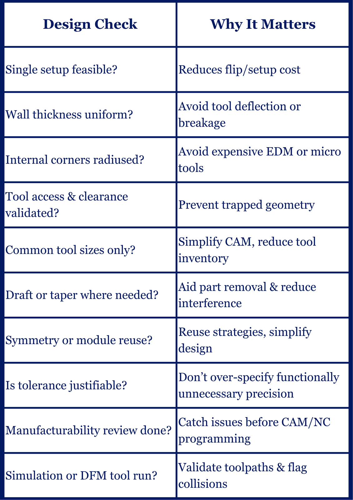
A Practical Checklist (Designer-Focused)
Before handing off your CAD model to CAM or shop, run through this checklist:
Conclusion
The ultimate mark of a sophisticated designer is not a beautiful rendering but a design that sails smoothly through production. The transition from CAD to CNC is a proving ground where theoretical elegance meets physical constraints. By proactively adopting the mindset of a machinist and rigorously applying Design for Manufacturability (DFM) principles like minimizing setups, using generous radio, and respecting tool access, you move beyond merely making a part look good. You ensure it can be done efficiently, affordably, and on time. Balancing the trade-offs between aesthetic complexity and machining simplicity early in the design phase is the most impactful decision you will ever make in product development. Great designers don't just make parts that look perfect; they make parts that can be made perfectly.
Ready to move your procurement from spreadsheets to strategy? AI is no longer optional — it’s the backbone of modern buying. Empower your procurement team with intelligent sourcing, real-time spend visibility, and smarter decision-making. Visit Trustbridge.pro to explore buyer resources, case studies, and solutions designed to help procurement professionals lead with confidence.
Frequently Asked Questions (FAQ)
1. What is the single biggest design factor driving up CNC manufacturing costs?
The number of machine setups required is often the largest cost driver. Minimizing part reorientation by grouping features can dramatically reduce both time and expense, directly impacting the final part price.
2. Why are sharp internal corners problematic for CNC milling?
Cutting tools have a round geometry, meaning they physically cannot produce a perfect 90% internal corner. Requiring sharp corners necessitates expensive processes like EDM or custom micro-tools, increasing costs and lead time significantly.
3. How can I ensure proper tool access in deep pockets?
Designers should maintain a pocket depth-to-width ratio of no more than 6:1. Also, ensure the internal fillet radius is slightly larger than the radius of the largest end mill cutting the feature.
4. When should a designer begin conducting manufacturability checks?
Manufacturability checks should begin as early as the conceptual design phase. Catching an issue before the model is finalized prevents costly design iterations and wasted CAM programming time.